
Air conditioner air outlet structure and air conditioner

An air conditioner and air-conditioning technology, which is applied in air-conditioning systems, space heating and ventilation, space heating and ventilation details, etc., can solve problems such as uneven air outlet, small air outlet surface of air conditioner, and poor human comfort. Achieve the effect of uniform air outlet and ensure air outlet efficiency

Inactive Publication Date: 2017-02-15
GREE ELECTRIC APPLIANCES INC
View PDF16 Cites 9 Cited by
  • Summary
  • Abstract
  • Description
  • Claims
  • Application Information

AI Technical Summary

Problems solved by technology

[0002] Traditional air conditioners have a small air outlet surface and a high airflow velocity. The wind speed passing through the human body surface is higher than the minimum wind speed perceived by the human body. The aerodynamic noise is obvious and the human body feels poor comfort.
[0003] If the air outlet is set to supply air in a large area, the air will rush to the bottom of the channel due to inertia after entering the air flow channel at high speed after the fan does work, and will flow out from the lower end at high speed due to flow obstruction, and the upper end will be caused by internal high-speed air flow. The jet flow effect causes not only no air flow from the upper heat exchanger side, but even a "backflow phenomenon" in which the outside air is forced into the circulation channel, which not only produces uneven air flow, but also affects the air output efficiency of the air conditioner

Method used


Image

  • Air conditioner air outlet structure and air conditioner
  • Air conditioner air outlet structure and air conditioner
  • Air conditioner air outlet structure and air conditioner

Examples


Embodiment Construction

[0022] The present invention will be described in further detail below in conjunction with the accompanying drawings and specific embodiments, but not as a limitation of the present invention.

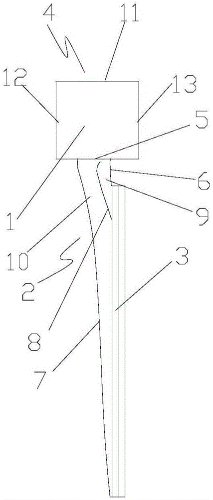
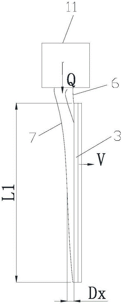
[0023] see in conjunction Figure 1 to Figure 4 As shown, according to the embodiment of the present invention, the air outlet structure of the air conditioner includes a fan 1, an air supply duct 2 and a heat exchanger 3, the fan 1 includes a fan air inlet 4 and a fan outlet 5, and the air supply duct 2 is connected to the fan At the air outlet 5, the front side wall 6 of the air supply duct 2 extends from the fan outlet 5 to the side of the heat exchanger 3 close to the fan outlet 5, and the rear side wall 7 of the air supply duct 2 extends from the fan outlet. 5 extends to the other side of the heat exchanger 3 away from the fan outlet 5, the heat exchanger 3 is arranged at the outlet of the air supply duct 2, and the cross section of the air supply duct 2 decreases along the direct...


PUM


Abstract

The invention discloses an air conditioner air outlet structure and an air conditioner. The air conditioner air outlet structure comprises a fan (1), an air supply duct (2) and a heat exchanger (3), wherein the fan (1) comprises a fan air inlet (4) and a fan air outlet (5), the air supply duct (2) is connected to the fan air outlet (5), the front side wall (6) of the air supply duct (2) extends to the side, close to the fan air outlet (5), of the heat exchanger (3) from the fan air outlet (5), and the rear side wall (7) of the air supply duct (2) extends to the other side, away from the fan air outlet (5), of the heat exchanger (3) from the fan air outlet (5). The heat exchanger (3) is arranged at an outlet of the air supply duct (2), and the section of the air supply duct (2) is gradually reduced in the direction away from the fan air outlet (5). The air conditioner air outlet structure is uniform in air output, and can effectively guarantee the air output efficiency of the air conditioner.

Description

technical field [0001] The invention relates to the technical field of air conditioning, in particular to an air outlet structure of an air conditioner and an air conditioner. Background technique [0002] The traditional air conditioner has a small air outlet surface and a high airflow velocity. The wind speed passing through the human body surface is higher than the minimum wind speed perceived by the human body. The aerodynamic noise is obvious and the human body feels poor comfort. [0003] If the air outlet is set to supply air in a large area, the air will rush to the bottom of the channel due to inertia after entering the air flow channel at high speed after the fan does work, and will flow out from the lower end at high speed due to flow obstruction, and the upper end will be caused by internal high-speed air flow. Due to the jet flow effect, not only can no air flow out from the upper side of the heat exchanger, but even a "backflow phenomenon" in which the external...

Claims


Application Information

Patent Timeline
Patent Type & Authority Applications(China)
IPC IPC(8): F24F1/00F24F13/06F24F13/08F24F13/30
CPCF24F1/0011F24F13/06F24F13/08F24F13/30
Inventor 朱芳勇熊军高旭
Owner GREE ELECTRIC APPLIANCES INC
Learn More