Dehumidifier and chassis component thereof

A technology for dehumidifiers and chassis, which is applied to refrigeration components, refrigerators, mechanical equipment, etc., and can solve problems such as pre-installation operations, low production efficiency, and inaccurate air temperature and humidity detection values

Active Publication Date: 2017-02-15
GREE ELECTRIC APPLIANCES INC
View PDF20 Cites 2 Cited by
  • Summary
  • Abstract
  • Description
  • Claims
  • Application Information

AI Technical Summary

Problems solved by technology

[0004] However, due to the close distance between the temperature and humidity sensor and the evaporator, this will bring the following disadvantages:
[0005] First of all, the temperature and humidity detected by the temperature and humidity sensor are affected by the change of the moisture state condensed on the surface of the evaporator, that is, the fluctuation of water evaporation and condensation, which makes the test value of the temperature and humidity s

Method used


Image

  • Dehumidifier and chassis component thereof
  • Dehumidifier and chassis component thereof
  • Dehumidifier and chassis component thereof

Examples


Embodiment Construction

[0037] The core of the invention is to provide a chassis assembly to improve detection accuracy. Another core of the present invention is to provide a dehumidifier with the above chassis assembly.

[0038] The following will clearly and completely describe the technical solutions in the embodiments of the present invention with reference to the accompanying drawings in the embodiments of the present invention. Obviously, the described embodiments are only some, not all, embodiments of the present invention. Based on the embodiments of the present invention, all other embodiments obtained by persons of ordinary skill in the art without making creative efforts belong to the protection scope of the present invention.

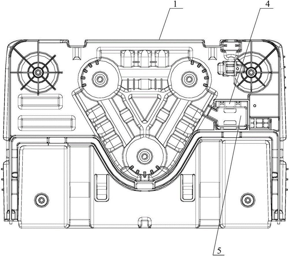
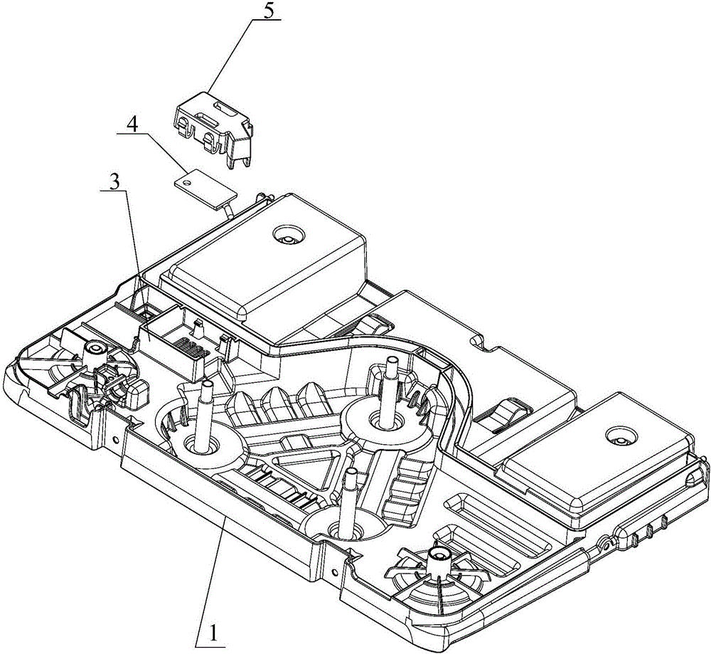
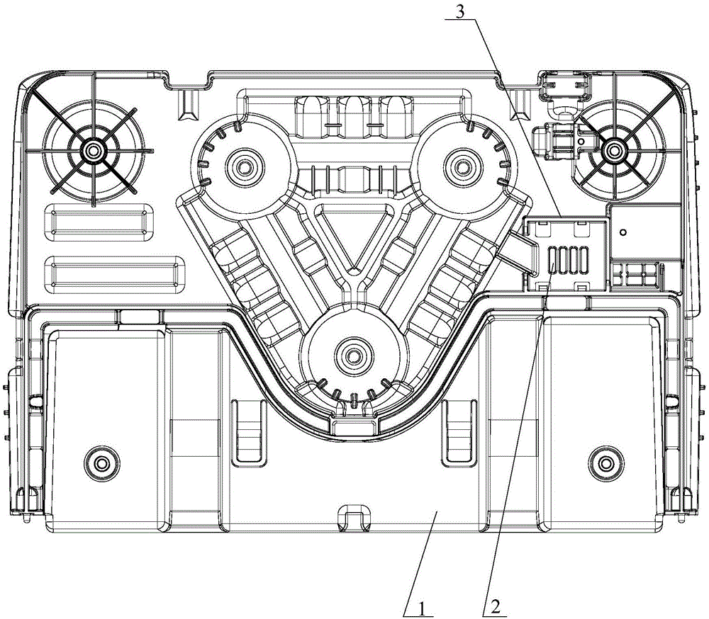
[0039] Such as Figure 1-Figure 6 As shown, the present invention discloses a chassis assembly, including a chassis 1 and a temperature and humidity sensor 4 . Wherein, the chassis 1 has a ventilation opening 2 capable of ventilating with the outside world, so as...


PUM


Abstract

The invention discloses a chassis component which comprises a chassis and a temperature and humidity sensor. The chassis component is characterized in that the temperature and humidity sensor is mounted on the chassis instead of an evaporator in the prior art; an air vent ventilating with the outside is formed in the chassis; and the temperature and humidity sensor obtains temperature and humidity parameters of air through acquiring temperature and humidity at the air vent. A mounting position of the temperature and humidity sensor is changed, that is the temperature and humidity sensor is mounted on the chassis far from the evaporator, so that the problem that water evaporation and condensation of the evaporator affects detection is solved, and the detection accuracy is improved. The invention also discloses a dehumidifier provided with the chassis component.

Description

technical field [0001] The invention relates to the technical field of air conditioning, in particular to a dehumidifier and its chassis assembly. Background technique [0002] The dehumidifier is a device for air treatment. Its working principle is that the humid air is sucked into the machine by the fan and passes through the heat exchanger. At this time, the water molecules in the air condense into water droplets, and the dry air after treatment is discharged out of the machine This cycle keeps the indoor humidity at a suitable relative humidity. [0003] In the existing dehumidifier, it includes a face shell and a main body, wherein a temperature and humidity sensor for detecting air temperature and humidity is installed on the surface of the evaporator of the main body through a bracket and is opposite to the air inlet of the face shell. The parameters are obtained by detecting the temperature and humidity at the air inlet, and the temperature and humidity sensor is co...

Claims


Application Information

Patent Timeline
IPC IPC(8): F24F3/14F24F11/00F24F13/30F24F13/08F25B39/02
CPCF24F3/14F24F11/30F24F13/082F24F13/30F24F2110/10F24F2110/20F25B39/02F24F2003/144
Inventor 马江辉黄晓清姚刚梁耀祥何炜谷中锋侯帅飞王坦
Owner GREE ELECTRIC APPLIANCES INC
Why Eureka
Try Eureka