
A method for fault detection of motor stator winding

A motor stator and stator winding technology, applied in electrical winding testing, radiation pyrometry, electrical measurement, etc., can solve the problems of difficult follow-up repair, large winding damage, low detection accuracy, etc., achieve intuitive and accurate non-destructive positioning, reduce Hidden dangers, the effect of reducing costs

Active Publication Date: 2019-02-19
CSR ZHUZHOU ELECTRIC CO LTD
View PDF6 Cites 0 Cited by
  • Summary
  • Abstract
  • Description
  • Claims
  • Application Information

AI Technical Summary

Problems solved by technology

[0004] The technical problem to be solved by the present invention is to provide a motor stator winding fault detection method, which can solve the technical problems of low detection accuracy, low efficiency, large damage to the winding, and difficult subsequent repairs existing in the prior art

Method used


Image

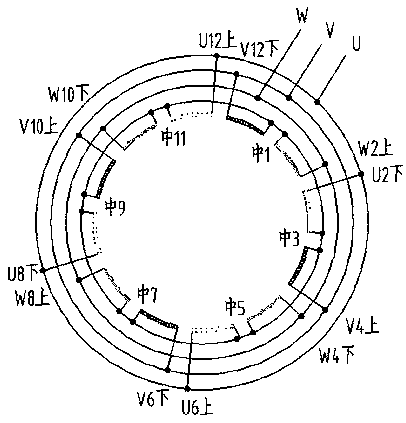
  • A method for fault detection of motor stator winding

Examples


Embodiment Construction

[0020] A motor stator winding fault detection method, energizing the motor stator winding (the current is about 4 times that of no-load), according to the abnormal temperature of the coil or coil group where the faulty lead wire is located compared with the rest of the coils (usually higher, after the lead wire is completely broken) Because there is no current passing, the temperature is low), use the temperature field observation screen of the infrared thermal imager to observe and record the temperature distribution characteristics of the entire winding intuitively and quickly, and then analyze and judge the fault lead.

[0021] The infrared thermal imager uses the infrared detector and the optical imaging objective lens to receive the infrared radiation energy distribution pattern of the measured target and reflect it on the photosensitive element of the infrared detector to obtain an infrared thermal image, which is consistent with the thermal image on the surface of the obj...


PUM


Abstract

The invention discloses a motor stator winding fault detection method. A motor stator winding is electrified; at the same time, an infrared thermal imager is used to observe the stator winding, and further an infrared thermal image of the observed stator winding and a temperature distribution feature of the whole stator winding are obtained; according to a principle that the temperature a coil or coil assembly in which a fault lead is placed is higher or lower than that of other coils as well as an obtained observation result, the fault position is analyzed and determined. The method is mainly used to detect hidden winding faults as three-phase DC resistance imbalance caused by that a welding joint of the motor stator winding is fractured or has cracks, can confirm the position of the fault lead efficiently, visually and accurately without loss, and reduces the fault detecting and processing cost of a motor greatly.

Description

technical field [0001] The invention relates to the technical field of detection, in particular to the field of motor winding fault detection and maintenance. Background technique [0002] Faults in motor windings, such as unbalanced three-phase resistance, are usually caused by cracks or breaks in the leads between the winding coils and the conductive rings or connecting wires. In the early stages of a fault, it is difficult to locate the fault lead intuitively, accurately and non-destructively due to the outer insulation wrap. The usual method is to cut the lead wires, and then determine the location of the faulty lead wires phase by phase, group by group, and one by one by measuring the DC resistance, but the follow-up repair of this method is difficult and has high hidden dangers. In many cases, after fault statistics and analysis are done, the winding will be pulled out and scrapped as a whole, which is extremely wasteful. [0003] In the prior art, the Chinese invent...

Claims


Application Information

Patent Timeline
Patent Type & Authority Patents(China)
IPC IPC(8): G01R31/06G01J5/00
CPCG01J5/0096G01J2005/0077G01R31/72
Inventor 兰涛凌翠平韦在凤卢明明刘波宏李赛
Owner CSR ZHUZHOU ELECTRIC CO LTD
Learn More