A vehicle detection antenna

An antenna and vehicle-mounted technology, applied in the field of vehicle-mounted detection antennas, can solve problems such as the inability to realize long-distance air-to-air signal detection, the short range of ultrashort-wave detection equipment, and the difficulty in meeting the needs of long-distance detection, etc., to achieve folding and easy storage Convenience, meet the expansion technical indicators, and have the effect of versatility

Active Publication Date: 2019-01-15
36TH RES INST OF CETC
View PDF7 Cites 0 Cited by
  • Summary
  • Abstract
  • Description
  • Claims
  • Application Information

AI Technical Summary

Problems solved by technology

[0003] However, the ultrashort wave detection equipment in active service, most of the ultrashort wave detection antenna array adopts the omnidirectional 7-element or 5-element circular array design. The gain of the array is relatively low, which is difficult to meet the needs of long-distance detection
[0004] The ultrashort-wave detection equipment in active service has a short range, and the ultrashort-wave direction-finding antenna is small in size and low in accuracy, so it cannot detect long-distance air signals, and it does not have the ability to cooperate with other positions to rendezvous and locate important tactical targets, which affects the The ability to judge target attributes seriously restricts the role of the vehicle crew on the battlefield

Method used


Image

  • A vehicle detection antenna
  • A vehicle detection antenna
  • A vehicle detection antenna

Examples


Embodiment Construction
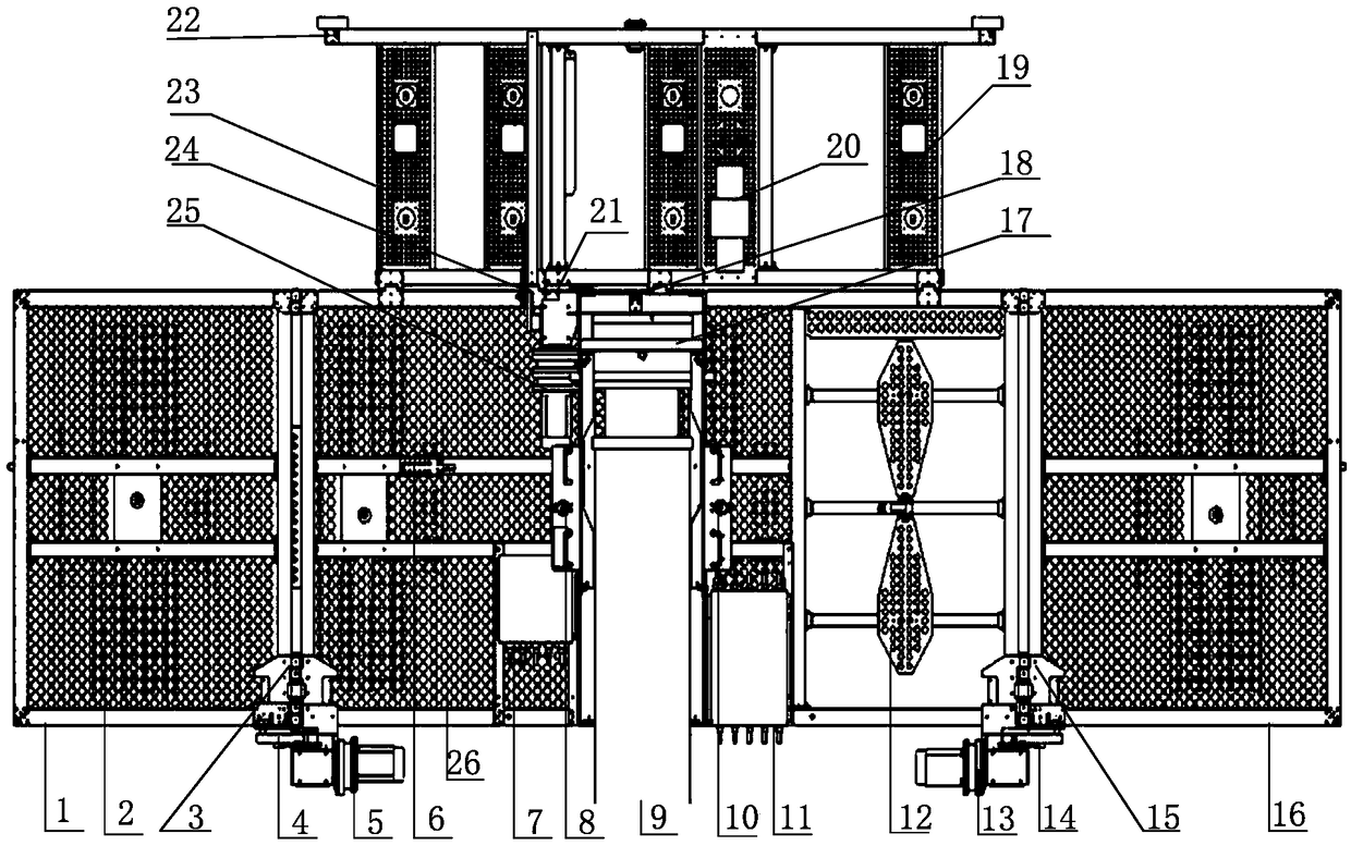
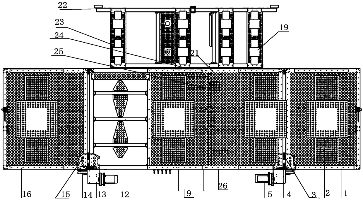
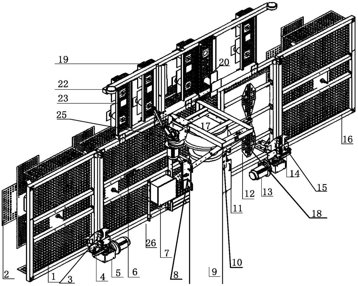
[0019] The technical idea of ​​the present invention is: aiming at the deficiencies of the existing equipment, the present invention provides a design different from the conventional vehicle-mounted platform antenna array. Overcoming the size limitation of the vehicle-mounted platform, the antenna baseline can be longer and the detection accuracy can be improved. In addition, the horizontal antenna array is composed of a symmetrical dipole directional antenna unit with a reflective surface, and the antenna array has higher gain and greater sensitivity. It not only meets the technical index requirements of wide-band coverage, large-size baseline, high-gain reception, and high-precision direction finding, but also meets the user's needs for automatic unfolding and folding, automatic lifting and rotation, and can double the combat power of mobile equipment.

[0020] In order to make the object, technical solution and advantages of the present invention clearer, the implementation ...


PUM


Abstract

The invention discloses a vehicle-mounted detection antenna. The vehicle-mounted detection antenna comprises a low frequency band directional antenna array and a high frequency band directional antenna array, wherein each of the low frequency band directional antenna array and the high frequency band directional antenna array comprises a horizontal antenna array with a reflective surface, and a sensing antenna used for front and rear direction finding ambiguity resolution, and the horizontal antenna array is composed of symmetric dipole directional antenna units; reflective plates of the low frequency band directional antenna array comprise a reflective plate capable of rotating leftwards, a reflective plate fixed in the middle and a reflective plate capable of rotating rightwards, which are sequentially arranged in the horizontal direction; a reflective plate of the high frequency band directional antenna array comprises a reflective plate capable of rotating upwards; and the reflective plate capable of rotating leftwards, the reflective plate capable of rotating rightwards and the reflective plate capable of rotating upwards can be folded or unfolded with respect to the reflective plate fixed in the middle. The detection antenna provided by the invention is integrally designed in a limited space of a vehicle platform, high requirements on unfolding indexes, and use requirements on folding for easy storage, mobile transportation and the like are met, and the antenna is general for remote detection of the vehicle platform.

Description

technical field [0001] The invention relates to the technical field of antennas, in particular to a vehicle-mounted detection antenna. Background technique [0002] On the high-mobility vehicle-mounted platform, due to the limited installation size of the platform and the constraints of road and rail transportation maneuvers, in the field of vehicle-mounted communication signal detection antenna arrays, it is necessary to meet the requirements of wide-band coverage, large-size baseline, high-gain reception, and high-precision direction finding. It meets the requirements of the technical indicators of the user, and also meets the user's needs for automatic unfolding, folding, automatic lifting and rotation, which is an urgent demand for the integration of vehicle-mounted communication detection antenna arrays. [0003] However, the ultrashort wave detection equipment in active service, the ultrashort wave detection antenna array mostly adopts the omnidirectional 7-element or ...

Claims


Application Information

Patent Timeline
Patent Type & Authority Patents(China)
IPC IPC(8): H01Q1/08H01Q1/32H01Q15/14H01Q21/00H01Q21/30
CPCH01Q1/084H01Q1/3216H01Q15/14H01Q21/00H01Q21/30
Inventor 唐力强叶建意罗冰
Owner 36TH RES INST OF CETC
Why Eureka
Try Eureka