Peak-current-mode Buck circuit sub-harmonic oscillation elimination method based on slope compensation method

A technology of peak current mode and sub-harmonic oscillation, applied in the direction of output power conversion device, DC power input conversion to DC power output, electrical components, etc., can solve the problems of current steady-state oscillation and damage to system stability, etc., to achieve The effect of eliminating subharmonic oscillation and improving stability

Inactive Publication Date: 2017-02-15
HEILONGJIANG ELECTRIC POWER RES INST +1
View PDF3 Cites 1 Cited by
  • Summary
  • Abstract
  • Description
  • Claims
  • Application Information

AI Technical Summary

Problems solved by technology

[0005] The purpose of the present invention is to solve the problem that when the PWM duty cycle of the PWM controller Uc3842 is greater than 50%, the disturbance of the current will cause the phenomenon ...

Method used


Image

  • Peak-current-mode Buck circuit sub-harmonic oscillation elimination method based on slope compensation method
  • Peak-current-mode Buck circuit sub-harmonic oscillation elimination method based on slope compensation method
  • Peak-current-mode Buck circuit sub-harmonic oscillation elimination method based on slope compensation method

Examples


specific Embodiment approach 1

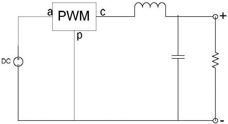
[0022] Specific embodiment one: In the peak current mode Buck circuit subharmonic oscillation elimination method based on the slope compensation method described in this embodiment, the reference voltage signal is input to the same input terminal of the PWM comparator, and the reverse direction of the PWM comparator of the Buck circuit The input terminal inputs a current feedback signal, and the reverse input terminal of the PWM comparator also inputs a voltage signal with a positive slope for compensating the slope of the current feedback signal.

specific Embodiment approach 2

[0023] Specific implementation mode two: combination Figure 1 to Figure 6 This embodiment is described in detail. This embodiment is a further description of the peak current mode Buck circuit subharmonic oscillation elimination method based on the slope compensation method described in the first embodiment. In this embodiment, the voltage signal with a positive slope is as follows device generated, the device includes:

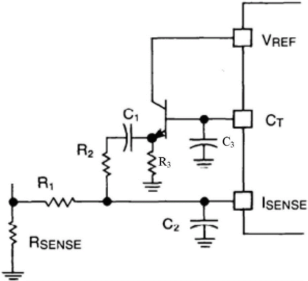
[0024] Resistance R SENSE , resistance R 1 , resistance R 2 , resistance R 3 , electrolytic capacitor C 1 , electrolytic capacitor C 2 and electrolytic capacitor C 3 and triode;

[0025] Resistance R SENSE One end of the ground, resistor R SENSE The other end of the resistor R 1 Connected to one end of the resistor R SENSE and resistor R 1 The common terminal of the positive slope voltage signal is connected to the negative input terminal of the PWM comparator, and the resistor R 1 The other end of the resistor R 2 One end of the electrolytic c...

specific Embodiment approach 3

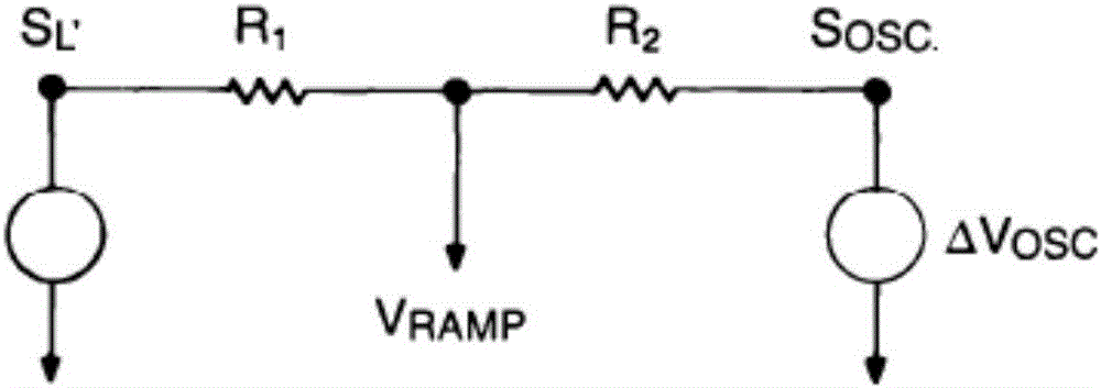
[0042] Specific embodiment three: This embodiment is a further description of the peak current mode Buck circuit sub-harmonic oscillation elimination method based on the slope compensation method described in specific embodiment two. In this embodiment, the resistor R 2 The resistance R2 is:

[0043]

[0044] R1 is the resistor R 1 ΔVosc is the voltage differential at osc point, VS(L) is the voltage at SL point, and M is the slope compensation coefficient.


PUM


Abstract

The invention discloses a peak-current-mode Buck circuit sub-harmonic oscillation elimination method based on a slope compensation method. The peak-current-mode Buck circuit subharmonic oscillation elimination method relates to the Buck circuit sub-harmonic oscillation elimination technology, and aims to solve the problem that current disturbance can cause a steady-state oscillation phenomenon and damage the stability of the system when a PWM duty ratio of a PWM controller Uc3842 is greater than 50%. A non-inverting input end of a PWM comparator inputs a reference voltage signal, an inverting input end of the PWM comparator inputs a current feedback signal, and the inverting input end of the PWM comparator further inputs a positive-slope voltage signal used for compensating for a slope of the current feedback signal. The peak-current-mode Buck circuit sub-harmonic oscillation elimination method is suitable for eliminating the sub-harmonic oscillation of a Buck circuit.

Description

technical field [0001] The invention relates to the subharmonic oscillation elimination technology of a Buck circuit. Background technique [0002] In occasions such as household appliances and industrial production, it is necessary to convert power frequency alternating current into direct current and then utilize it. As the basic topology of DC-DC, the non-isolated Buck circuit is widely used in the above occasions due to its simple structure and low cost. Use peak current control PWM mode. [0003] The current mode PWM controller Uc3842 includes two feedback loops: a voltage outer loop formed by an error amplifier that receives output voltage sampling signals and a current inner loop formed by a PWM comparator that receives loop peak current sampling signals. Different from the voltage mode, the current mode directly controls the peak value of the output current, which has the advantages of fast response, preventing magnetic saturation caused by bias magnetism, and simp...

Claims


Application Information

Patent Timeline
IPC IPC(8): H02M3/158H02M1/14
CPCH02M1/143H02M3/1582
Inventor 祖光鑫于海洋郭袅马莹刘岩蔡银哿佟瑶王文亭
Owner HEILONGJIANG ELECTRIC POWER RES INST
Why Eureka
Try Eureka