Industrial Ethernet switch with optical power detection
An optical power detection and Ethernet technology, applied in electromagnetic wave transmission systems, electrical components, transmission systems, etc., can solve problems such as inability to know the working state of optical fibers in advance, low detection and troubleshooting efficiency, and complex operating environments, so as to facilitate failures. The effect of positioning, easy monitoring, and easy viewing
- Summary
- Abstract
- Description
- Claims
- Application Information
AI Technical Summary
Problems solved by technology
Method used
Image

Examples
no. 1 example
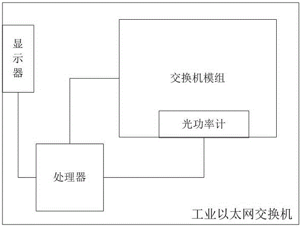
[0024] Such as figure 2 , the industrial Ethernet switch provided by the present invention includes an optical power meter and a processor.
[0025] The optical power meter is used to detect the optical power of the optical signal input by the optical port of the industrial Ethernet switch; the processor is used to calculate the difference between the optical power and the light receiving sensitivity, if the difference between the two is less than the margin setting value Then, the alarm information of insufficient received power headroom and the corresponding optical fiber number are sent to the management server through the network.
[0026] Optical receiving sensitivity is also called the minimum received optical power. For optical fibers with a bandwidth of 100MHz, its typical sensitivity value is usually -35dBm, and for optical fibers with a bandwidth of 1000MHz, its typical sensitivity value is usually -25dBm.
[0027] Preferably, a general alarm is issued when the dif...
no. 2 example
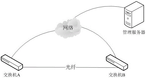
[0030] The power loss of the optical fiber is also an important indicator for detection. In another embodiment, when the switch sends a signal, it will also transmit its own transmitted optical power and output data to the opposite switch through the optical fiber. The processor in the opposite switch also It is used to extract the transmitted optical power of the sending end from the optical signal input by the optical port of the industrial Ethernet switch, calculate the difference between the optical power output by the optical power meter and the transmitted optical power, and divide the difference by the fiber length to obtain the actual fiber loss per unit length , if the value is greater than the loss setting value, the alarm information of excessive fiber optical power loss and the corresponding fiber number will be sent to the management server through the network.
[0031] The length of the optical fiber and the standard value of loss per unit length of the optical fi...
no. 3 example
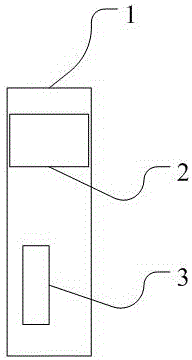
[0034] In order to facilitate on-site operators to check, this embodiment also includes a display screen 2 arranged on the industrial Ethernet switch case 1, see image 3 The processor has a signal connection with the display screen; the processor is used to display the alarm information of insufficient received power margin, the alarm information of excessive fiber optical power loss and the received optical power on the display screen.
PUM
 Abstract
Description
Claims
Application Information
 - R&D
- Intellectual Property
- Life Sciences
- Materials
- Tech Scout
- Unparalleled Data Quality
- Higher Quality Content
- 60% Fewer Hallucinations
Browse by: Latest US Patents, China's latest patents, Technical Efficacy Thesaurus, Application Domain, Technology Topic, Popular Technical Reports.
© 2025 PatSnap. All rights reserved.Legal|Privacy policy|Modern Slavery Act Transparency Statement|Sitemap|About US| Contact US: help@patsnap.com