
Removable dotting feeding assembly of PCB dotting device

A PCB circuit board and circuit board technology, which is applied in the direction of assembling printed circuits with electrical components, can solve the problems of automatic solder feeding, non-detachable structure, and poor printing effect, so as to improve heat utilization rate, convenient printing, connection and Take-and-place convenience

Inactive Publication Date: 2017-02-15
CHENGDU YANXINGGUO TECH CO LTD
View PDF0 Cites 0 Cited by
  • Summary
  • Abstract
  • Description
  • Claims
  • Application Information

AI Technical Summary

Problems solved by technology

[0004] Based on the above technical problems, the present invention provides a detachable dotting and feeding assembly of a PCB circuit board dotting device, which can do dots to multiple potential connection points at the same time, and it is a detachable structure that can continuously and quantitatively feed materials, thereby solving the problem of In the past, the multi-potential connection points were dotted separately, resulting in dot error, poor dot effect, non-detachable structure and technical problems that the solder could not be fed automatically.

Method used


Image

  • Removable dotting feeding assembly of PCB dotting device
  • Removable dotting feeding assembly of PCB dotting device
  • Removable dotting feeding assembly of PCB dotting device

Examples


Embodiment Construction

[0027] The present invention will be further described below in conjunction with the accompanying drawings. Embodiments of the present invention include, but are not limited to, the following examples.

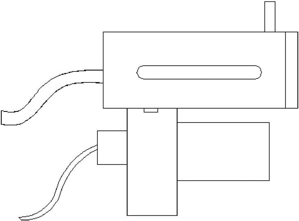
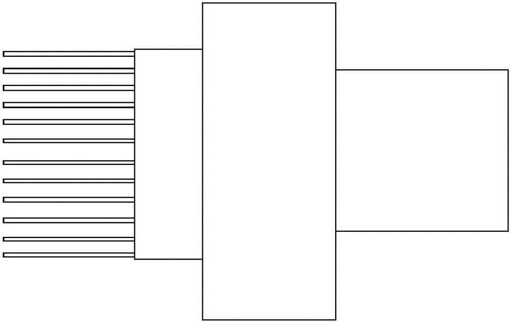
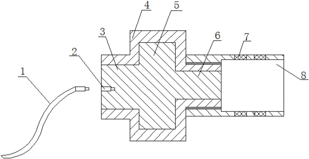
[0028] Such as Figure 1-Figure 5 As shown, the detachable dotting feeding assembly of the PCB circuit board dotting device includes a dotting joint and a solder feeding device that is clamped on the dotting joint;

[0029] in,

[0030] The dotting joint includes a metal heat-conducting block 5, and the two sides of the metal heat-conducting block 5 protrude outward to form a connecting head 3 and a positioning head 6 respectively. A plurality of metal heat conduction sheets 1 are plugged in. The cross section of the metal heat conduction sheets 1 is an S-shaped curve structure and its end section is a sharp angle. Inlaid with a plurality of permanent magnets 7.

[0031] The solder feeding device includes a heat-conducting metal solder cylinder 10 for filling solder, one e...


PUM


Abstract

The invention relates to a removable dotting feeding assembly of a PCB dotting device. The removable dotting feeding assembly comprises a dotting joint and a solder feeding device; the dotting connector comprises a metal thermal conduction block; a connection head and a positioning head are formed on the metal thermal conduction block; a plurality of insertion holes are linearly and uniformly formed at one end surface of the connection head; a plurality of metal thermal conduction sheets are inserted into the insertion holes; the external screw thread of the positioning head is connected with a heat insulating connection cylinder; a plurality of permanent magnets are embedded in the heat insulating connection cylinder; the solder feeding device comprises a thermal conduction metal solder cylinder; one end of the thermal conduction metal solder cylinder is provided with a threaded sealing cover; the other end of the thermal conduction metal solder cylinder is communicated with metal hoses; the thermal conduction metal solder cylinder is further provided with a filtering plate; the thermal conduction metal solder cylinder is provided with a transparent observation strip; the circumferential surface of the thermal conduction metal solder cylinder is provided with a thermal conduction metal elastic clamping buckle; and the thermal conduction metal solder cylinder is also provided with a gas communication pipe. With the assembly of the invention adopted, connection points of a plurality of potentials can be compressed and dotted simultaneously. The assembly has the advantages of small dotting error, continuous, simultaneous and quantitative feeding and timely solder transfer.

Description

technical field [0001] The invention relates to a dotting device for electronic equipment, and belongs to the field of electronic equipment processing. More specifically, the invention relates to a detachable dotting and feeding assembly of a dotting device for a PCB circuit board. Background technique [0002] During the processing and manufacturing process of PCB circuit boards of electronic equipment, many electric contacts, nodes, melting points and other potential connection points need to be marked with welding base points first. The base points are formed by melting solder and surfacing welding. The solder is made of aluminum wire in circles. During dotting, the staff feeds the wire with one hand and heats it with a dotting pen in the other hand, which makes the operation extremely inconvenient. Sometimes, the wire is not delivered in time and the dot is incomplete. It has brought a lot of inconvenience and problems to the basic management. [0003] In order to do th...

Claims


Application Information

Patent Timeline
Patent Type & Authority Applications(China)
IPC IPC(8): H05K3/34
CPCH05K3/34
Inventor 魏霁烁柏雅惠
Owner CHENGDU YANXINGGUO TECH CO LTD
Learn More