Torque transmission device for a hybrid vehicle

A hybrid vehicle and torque transmission technology, which is applied to the layout of multiple different prime movers of hybrid vehicles and general power plants, motor vehicles, etc., can solve problems that are difficult and will not meet the isolation requirements, and achieve saving effect of space

Active Publication Date: 2017-02-15
SCHAEFFLER TECH AG & CO KG
View PDF5 Cites 12 Cited by
  • Summary
  • Abstract
  • Description
  • Claims
  • Application Information

AI Technical Summary

Problems solved by technology

This in turn leads to having to use a sub-optimally dimensioned or too small main damper, w

Method used


Image

  • Torque transmission device for a hybrid vehicle
  • Torque transmission device for a hybrid vehicle

Examples


Embodiment Construction

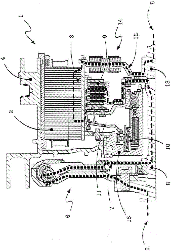
[0033] figure 1 A torque transmission device according to an embodiment of the invention is shown. First, we can see the stator 2 and rotor 3 of the motor 1 integrated in the torque transmission device. The stator 2 of the electric machine 1 is arranged in a stator housing 4, which currently simultaneously forms the housing 4 of the torque transmission device. In addition, the flow of force or moment can be seen, which is shown in the form of a dashed line 5 through the torque transmission device. The torque enters from the crankshaft via the arc spring damper 6 on the crankshaft side (on the left side of the drawing) and is introduced into the torque transmission device via the drive flange 7 and the drive shaft 8.

[0034] The torque from the drive shaft 8 arrives in a disconnect clutch 9 implemented here as a diaphragm clutch, which is operated via a disc spring 11 and a clutch actuator 10. Instead of a diaphragm clutch, for example, a single-plate dry clutch can also be arr...


PUM


Abstract

The invention relates to a torque transmission device that is to be arranged in a drive train of a hybrid vehicle comprising an internal combustion engine, a transmission and an electric machine, the electric machine being arranged in the torque transmission device. The torque transmission device comprises a disconnect clutch with clutch actuation, for decoupling the internal combustion engine from the transmission, and comprises a primary torsional vibration damper on the crankshaft side. The invention is characterised by a secondary torsional vibration damper arranged on the transmission side, radially and axially inside the rotor and directly on the transmission-side output flange of the torque transmission device. The invention allows the installation space for the crankshaft-side primary torsional vibration damper to be increased, such that said damper can be optimally designed. In torque transmission devices which originally have no secondary damper, the design of the primary damper can be smaller and more compact since the secondary damper supports the vibration damping. Since the secondary damper is arranged inside the rotor of the electric machine and directly on the transmission-side output flange of the torque transmission device, said damper requires only minimal or no additional installation space. This leaves surplus installation space which can be used, for example, to reduce the size of the torque transmission device, in particular to axially shorten said device, or be used to increase the size of the electric machine.

Description

Technical field [0001] The present invention relates to a torque transmission device according to the preamble of claim 1 for arrangement in a drive train of a hybrid vehicle. Background technique [0002] Torque transmission devices of the type mentioned at the beginning are often used or required in the automotive field in many cases for the controllable and possibly separable transmission of forces between the internal combustion engine, the electric machine and the transmission. To this end, a torque transmission device of the type mentioned at the beginning assumes the function of transmitting torque from the internal combustion engine and / or from the electric machine to the driven shaft or to the transmission on the one hand, and on the other hand between the internal combustion engine, the transmission and / or the electric machine The function of reducing torsional vibration. [0003] The torque transmission device can additionally be set up for starting the internal combust...

Claims


Application Information

Patent Timeline
IPC IPC(8): F16F15/12B60K6/38
CPCB60K6/38F16F15/1207F16D25/0638F16D3/12F16F15/12B60K6/40B60K6/26B60K6/387Y10S903/906Y10S903/914Y02E10/72F16D25/087F03D17/00F03D1/0675B60Y2200/92B60Y2400/424B60Y2400/60F16D13/52F16D2300/22H02K7/02H02K7/10
Inventor 安德烈亚斯·特兰肯舒威利·鲁德弗洛里安·纳赫特曼多米尼克·恩格尔曼
Owner SCHAEFFLER TECH AG & CO KG
Why Eureka
Try Eureka