Centrifugal powder particle mixing device

A mixing device and centrifugal technology, applied in the field of separation and mixing devices, to achieve the effects of high mixing efficiency, small damage and simple operation

Active Publication Date: 2017-02-22
NORTHWEST UNIV(CN)
View PDF10 Cites 4 Cited by
  • Summary
  • Abstract
  • Description
  • Claims
  • Application Information

AI Technical Summary

Problems solved by technology

[0003] The technical problem to be solved by the present invention is to overcome the shortcomings of existing powder particle mixing devices, ...

Method used


Image

  • Centrifugal powder particle mixing device
  • Centrifugal powder particle mixing device
  • Centrifugal powder particle mixing device

Examples


Embodiment 2

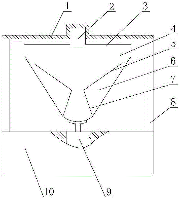
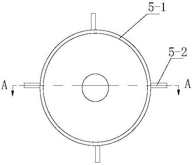
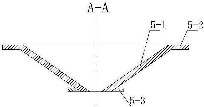
[0022] In this embodiment, the structure of the powder mixing tank 4 is that the inverted conical cylinder is integrated with the outer convex spherical bottom. The ratio of the large diameter to the small diameter of the conical cylinder is 1.5, and the lower screen 7, the upper screen 6, and the retaining cylinder 5 are arranged in the powder mixing tank 4 from bottom to top, and the angle between the busbar of the lower screen 7 and the axis is 45° , the included angle between the busbar of the retaining cylinder 5 and the axis is 35°, the diameter ratio of the diameter of the large end face of the retaining cylinder 5 to the small end face is 1.5, and the mesh diameter of the lower screen 7 and the upper screen 6 is 2mm .

[0023] The other components and the connection relationship of the components are the same as in Embodiment 1.

Embodiment 3

[0025] In this embodiment, the structure of the powder mixing tank 4 is that the inverted conical cylinder is integrated with the outer convex spherical bottom. The ratio of the large diameter to the small diameter of the conical cylinder is 3, and the lower screen 7, the upper screen 6, and the retaining cylinder 5 are arranged in the powder mixing tank 4 from bottom to top, and the angle between the busbar of the lower screen 7 and the axis is 65° , the included angle between the 5 generatrixes of the retaining cylinder and the axis is 55°, the diameter ratio of the diameter of the large end face of the retaining cylinder 5 to the small end face is 3, and the mesh diameter of the lower screen 7 and the upper screen 6 is 5mm . The other components and the connection relationship of the components are the same as in Embodiment 1.


PUM

PropertyMeasurementUnit
Angleaaaaaaaaaa
Diameteraaaaaaaaaa

Abstract

The invention relates to a centrifugal powder particle mixing device. A motor is arranged on a middle part of a base; a powder mixing tank is arranged on a power output shaft of the motor; a lower screen, an upper screen and a baffle drum are successively arranged in the powder mixing tank from bottom to top; holes in same diameter are formed in the center of each of the lower screen, the upper screen and the baffle drum; slots are formed between the baffle drum and the four walls of the powder mixing tank; a powder mixing tank cover is arranged on the powder mixing tank; a short shaft which is integrally connected with the powder mixing tank cover is arranged at the center of the outer surface of the powder mixing tank cover; a support rod is arranged on the base; a positioning disc is arranged on the support rod; and a groove which is matched with the short shaft is formed in the middle part of the positioning disc. The centrifugal powder particle mixing device has the advantages of simple operation, low cost, less damage to powder crystals, high mixing efficiency and wide popularization and application in the field of chemical industry production.

Description

technical field [0001] The invention relates to a separation and mixing device, in particular to a powder particle mixing device with a rotating device in a fixed container. Background technique [0002] The mixing of powder particles is often encountered in chemical experiments and chemical production processes. The ultimate purpose of mixing is to ensure that the properties of the mixture do not change on the basis of uniform mixing, and no reaction between substances occurs. Therefore, the mixing process should try to avoid damage to the powder particles high-strength rolling. For example, when mixing organic crystals in the laboratory, if there is rolling during the mixing process, it is likely to cause changes in the structure of the crystals. In addition, substances with large density differences are difficult to mix uniformly at one time, and multiple mixing requires disassembly and reloading of the existing device, which is cumbersome. Contents of the invention ...

Claims


Application Information

Patent Timeline
IPC IPC(8): B01F9/10B01F3/18
CPCB01F23/60B01F29/15B01F29/4032B01F29/81
Inventor 于秋硕乔小艳齐敏李晓锐刘恒张溪彧马晓迅
Owner NORTHWEST UNIV(CN)
Why Eureka
Try Eureka