Refrigerator upper beam processing device with flip function

A technology for processing devices and refrigerators, applied in the direction of spraying devices, devices for coating liquid on the surface, coatings, etc., can solve the problems of high safety risks, poor strength of the turning mechanism, etc., and achieve the effect of convenient and simple operation

Active Publication Date: 2018-10-16
遵义鑫航通科技发展有限公司
View PDF10 Cites 0 Cited by
  • Summary
  • Abstract
  • Description
  • Claims
  • Application Information

AI Technical Summary

Problems solved by technology

[0006] The present invention intends to provide a refrigerator upper beam processing device with overturning function to solve the technical problems of poor strength and high safety risk of the existing overturning mechanism

Method used


Image

  • Refrigerator upper beam processing device with flip function
  • Refrigerator upper beam processing device with flip function
  • Refrigerator upper beam processing device with flip function

Examples


Embodiment 1

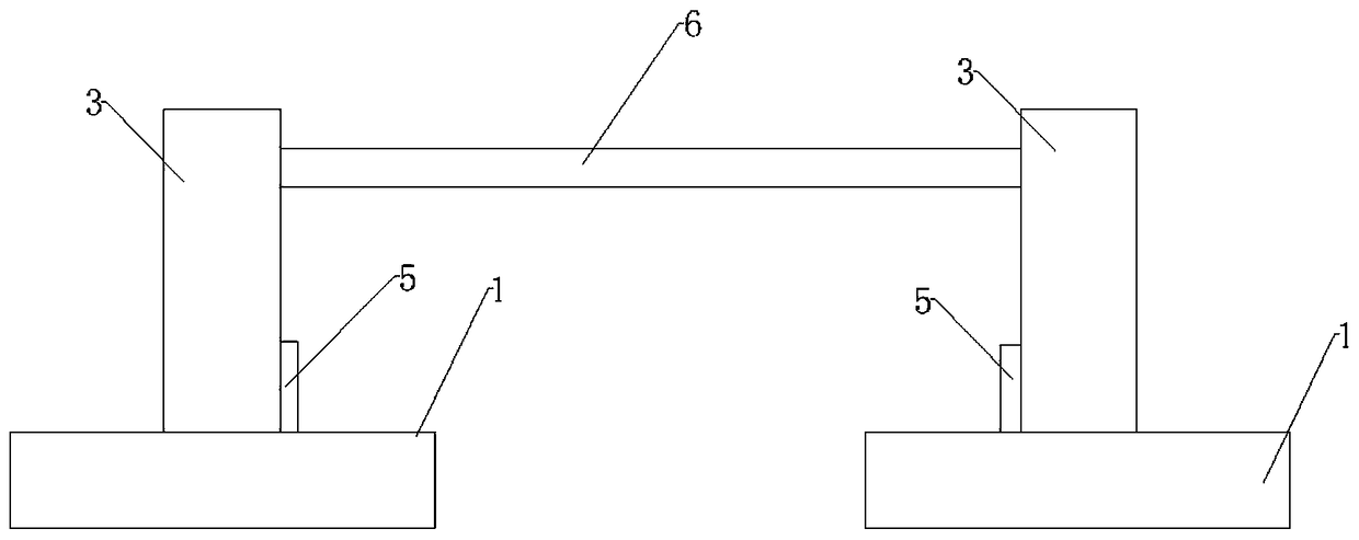
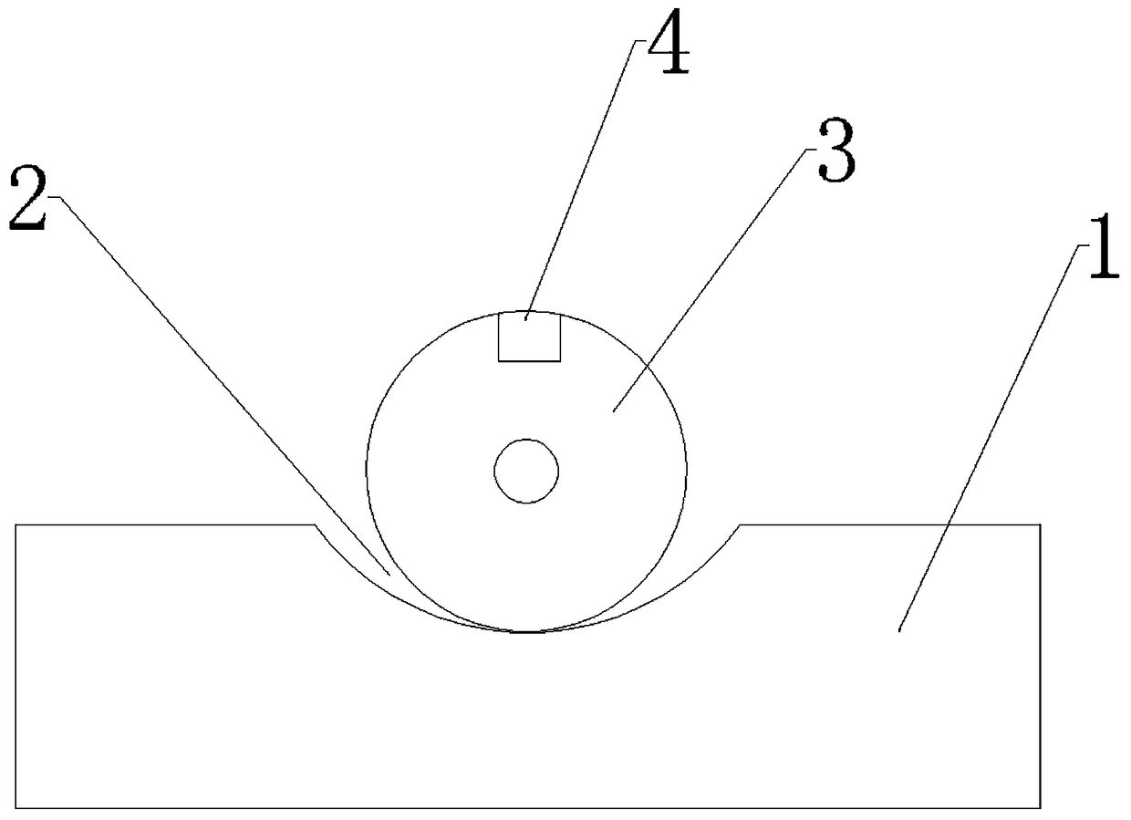
[0025] Such as figure 1 with image 3 As shown: the upper beam processing device of the refrigerator with flip function, including two processing tables 1, the middle part of the processing table 1 is provided with a chute 2, the cross section of the chute 2 is arc-shaped, and the roller 3 is installed in the chute 2, The roller 3 is in contact with the chute 2, and the roller 3 is provided with bristles, and the roller 3 can roll in the chute 2. The upper end of the roller 3 is provided with an opening groove 4 for fixing the upper beam workpiece 6, and the chute 2 is a The side is provided with elastic plate 5, and this elastic plate 5 is arranged on the inner side of two rollers 3, is provided with hairbrush on elastic plate 5.

[0026] The specific operation is as follows: when the upper beam workpiece 6 needs to be processed, insert the upper beam workpiece 6 into the open slot 4, use a spray gun to spray paint on one side of the upper beam workpiece 6 in one direction, ...

Embodiment 2

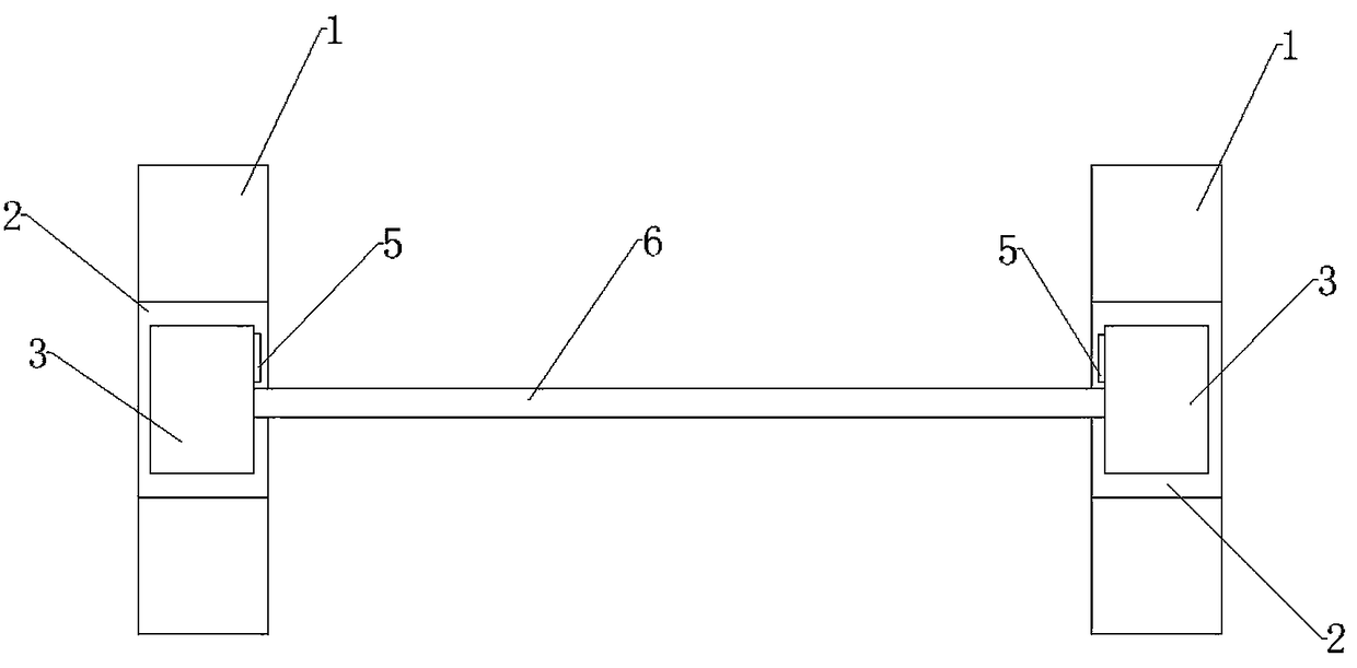
[0028] Such as figure 2 with image 3 As shown, the width of the roller 3 is less than the width of the chute 2, in order to allow the roller 3 to move its position on the chute 2 according to the length of the upper beam workpiece 6 when rolling. There is an elastic plate 5, and the elastic plate 5 is arranged on the inner side of the two rollers 3. Therefore, after processing, the roller 3 drives the upper beam workpiece 6 to rotate to the position of the elastic plate 5, and the elastic plate 5 intervenes in the opening groove 4, The elastic plate 5 is deformed by stress under the action of the upper beam workpiece 6; in order to restore the original shape, the elastic plate will apply an elastic restoring force to the upper beam workpiece 6, and the upper beam workpiece 6 will be lifted from the roller 3 under the action of the elastic restoring force. Ejection, rather than taking out the upper beam workpiece 6 from the roller 3 artificially.

Embodiment 3

[0030] Such as figure 2 Shown, the length of processing table 1 is generally greater than the length of chute 2, and in present embodiment 3, the length of processing table 1 is 2 times of this chute 2 lengths, the length of processing table 1 is set to the length of chute 2 2 times is for the convenience of placing the sprayed items on the processing table 1. There is no need to add an additional placing table or place it on the ground. If it is placed on the ground, the paint flowing out of the sprayed items will pollute the ground.


PUM


Abstract

The invention discloses a device for machining a refrigerator upper bar with a rollover function. The device comprises two machining tables, and further comprises two rollers, wherein the two rollers are respectively mounted on the machining tables; sliding chutes where the rollers slide are formed in the machining tables; opening slots for mounting the refrigerator upper bar are formed in the two rollers; elastic plates which extend into the opening slots and enable the refrigerator upper bar to be extruded are arranged on the sliding chutes; and brushes for coating the refrigerator upper bar with paint are arranged on the elastic plates. Compared with the prior art, the device has the advantages that an upper bar workpiece can be driven by the rollers to roll over only by applying acting force to the rollers instead of applying a jack to enable the upper bar workpiece to roll over, and then is coated with the paint; and the operation is convenient and simple.

Description

technical field [0001] The invention belongs to the technical field of fixtures, in particular to a refrigerator upper beam processing device with a turning function. Background technique [0002] The upper beam of the refrigerator is an important load-bearing structural part of the refrigerator equipment. If there are many welding seams on the upper beam of the refrigerator, and the welding positions are inconsistent, it will directly affect the quality and bearing capacity of the structural parts. In order to ensure the welding quality of the workpiece, it is necessary to Adjust the workpiece to a suitable position by turning it over multiple times and at multiple angles to ensure that the weld seam is at the best welding angle. [0003] In the traditional processing technology, the main method of turning the workpiece is to use the lifting equipment to complete it. There are many problems in using the lifting equipment to turn the workpiece: 1) The turning angle is not ea...

Claims


Application Information

Patent Timeline
Patent Type & Authority Patents(China)
IPC IPC(8): B05B13/02B05C13/02B05C1/06B05C11/10
CPCB05B13/0221B05C1/06B05C11/1039B05C13/02
Inventor 王元清
Owner 遵义鑫航通科技发展有限公司
Why Eureka
Try Eureka