A flexible guiding photovoltaic power station walking device

A photovoltaic power station and walking device technology, applied in photovoltaic power generation, photovoltaic modules, electrical components, etc., can solve problems such as troublesome installation, slipping of traction ropes, and burned components

Inactive Publication Date: 2018-11-13
ANHUI TIANZHU GREEN ENERGY SCI & TECH
View PDF7 Cites 0 Cited by
  • Summary
  • Abstract
  • Description
  • Claims
  • Application Information

AI Technical Summary

Problems solved by technology

If dust adheres to the surface of the photovoltaic module, it will affect the light transmittance, and then affect the radiation received by the surface of the module, which will affect the power generation efficiency, and because the distance between the dust and the battery is very close, it will form a shadow, and it will Photovoltaic modules locally form a hot spot effect, which reduces the power generation efficiency of the modules, and even burns the modules. Therefore, keeping the photovoltaic modules clean is an effective way to ensure the maximum power generation capacity of the photovoltaic power station
[0003] The transmission mechanism of the existing photovoltaic module cleaning system is to set a traction transposition and a guide support device under the beam. The traction device is connected by two driving wheels and four guide wheels through a traction belt. One of the driving wheels is driven by a motor, and the other is driven by a motor. A driving wheel is driven by a synchronous belt as a driven wheel. The transmission mechanism of this structure requires high installation accuracy and is troublesome to install; moreover, when the direction of the traction rope is inclined downward, the friction between the guide wheel and the traction rope Larger, the traction rope does not run smoothly, and it is easy to cause the traction rope to heat up due to friction, causing the traction rope to slip during operation

Method used


Image

  • A flexible guiding photovoltaic power station walking device
  • A flexible guiding photovoltaic power station walking device
  • A flexible guiding photovoltaic power station walking device

Examples


Embodiment Construction

[0014] The invention will be further described below by means of drawings and specific embodiments. The specific embodiments described here are only for explaining the invention, and are not intended to limit the protection scope of the present invention.

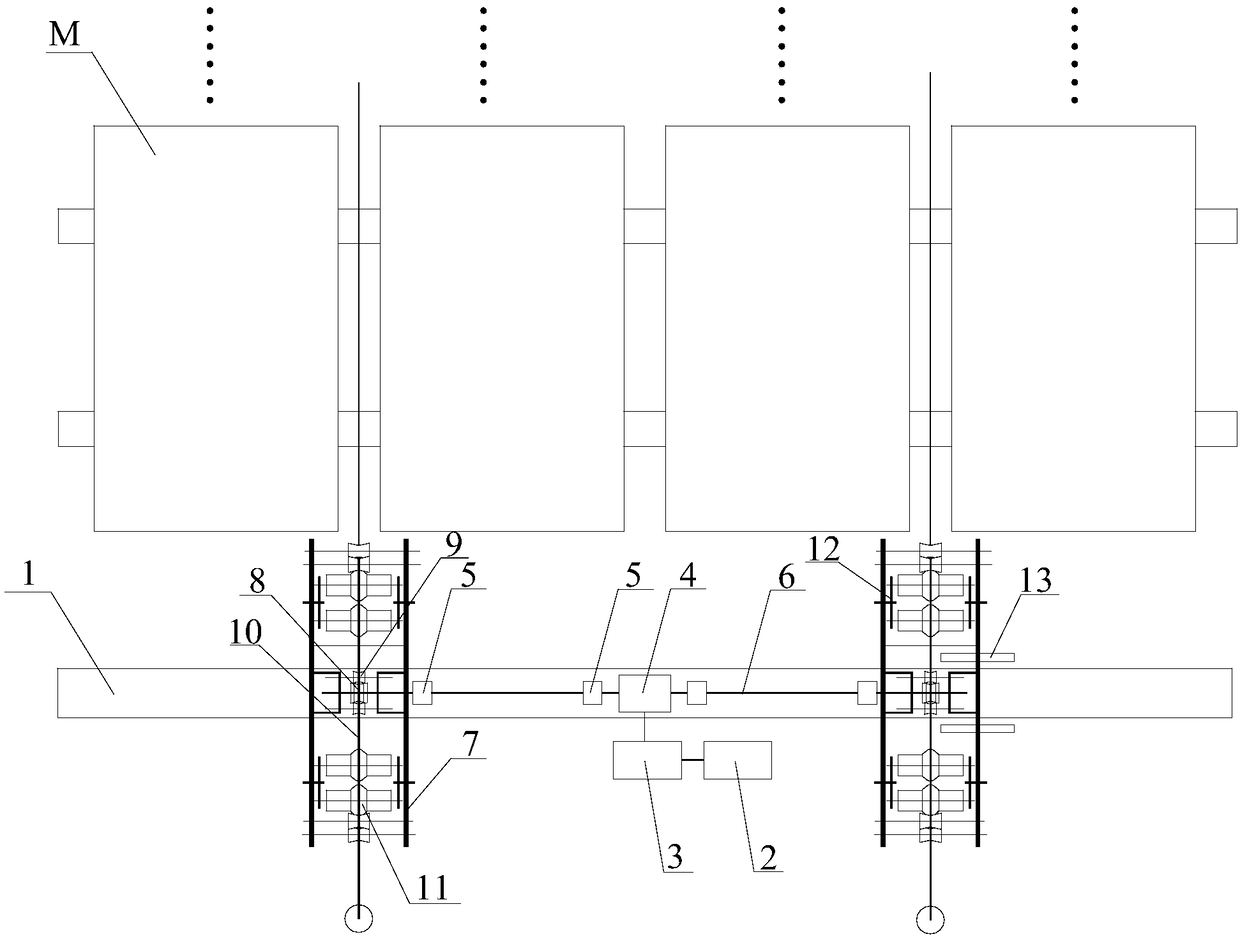
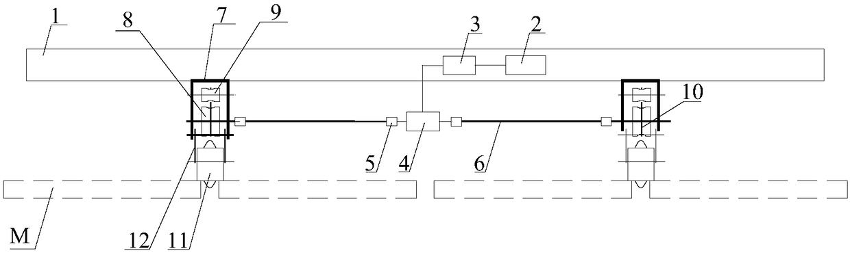
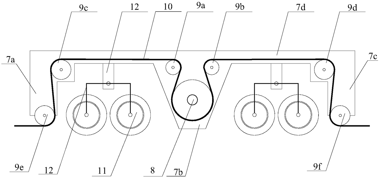
[0015] Schematic diagram of flexible guiding photovoltaic power station walking device, such as figure 1 — image 3 As shown, it includes a crossbeam 1, a biaxial motor 4, a transmission shaft 6, a driving wheel 8, a guide wheel 9 and a traction rope 10, the biaxial motor 4 is installed under the crossbeam 1, and the biaxial motor 4 is electrically connected to the controller 3, The controller 3 is electrically connected to the storage battery 2 , and both the controller 3 and the storage battery 2 are installed on the beam 1 .

[0016] The two motor shafts of the biaxial motor 4 are respectively connected with two driving wheels 8 on the left and right sides through the transmission shaft 6, and the driving wheel 8 is co...


PUM


Abstract

The invention discloses a flexibility oriented photovoltaic power station running gear which comprises a cross beam, a motor, a transmission shaft, driving wheels, six guide wheels and traction bands, wherein the motor is mounted below the cross beam; motor shafts of the motor is connected with the driving wheels through the transmission shaft; the driving wheels are connected with the guide wheels through the traction bands; the driving wheels and the guide wheels are fixed on support frames; the support frames are fixed below the cross beam; the six guide wheels are distributed on two sides of the driving wheels; two support rods are fixed at the lower parts of the support frames; a U-shaped wheel stand is fixed on each support rod; two support positioning wheels are mounted on each U-shaped wheel stand; and the support positioning wheels walk along gaps of photovoltaic modules. The flexibility oriented photovoltaic power station running gear is simple to mount, ensures that a brush cleaner runs in an unbiased manner, and prevents the photovoltaic modules from being in contact with a hard object and scratched.

Description

technical field [0001] The invention relates to a walking device, in particular to a flexible guiding photovoltaic power station walking device suitable for a photovoltaic module cleaning system. Background technique [0002] Photovoltaic power generation is a clean energy that has been widely used all over the world. Photovoltaic modules are the source of electricity generated by solar power plants, and the efficiency of photovoltaic modules directly determines the power generation of solar power plants. If dust adheres to the surface of the photovoltaic module, it will affect the light transmittance, and then affect the radiation received by the surface of the module, which will affect the power generation efficiency, and because the distance between the dust and the battery is very close, it will form a shadow, and it will Photovoltaic modules locally form a hot spot effect, which reduces the power generation efficiency of the modules, and even burns the modules. Therefo...

Claims


Application Information

Patent Timeline
Patent Type & Authority Patents(China)
IPC IPC(8): B08B11/04H02S40/10
CPCB08B11/04H02S40/10Y02E10/50
Inventor 彭寿李凤光卢育发刘祥董庆国李倩
Owner ANHUI TIANZHU GREEN ENERGY SCI & TECH
Why Eureka
Try Eureka