Hot rolling work roll water scraping fuel injection system and method

A technology of oil injection system and work roll, which is applied in the direction of rolls, metal rolling, manufacturing tools, etc. It can solve the problems of unfavorable work rolls, damage, broken belts and rolls, etc., to improve the effect of wiping water and lubricating the roll gap , avoid the impact damage of strip steel, and optimize the effect of occupying space

Active Publication Date: 2017-02-22
WISDRI ENG & RES INC LTD
View PDF7 Cites 5 Cited by
  • Summary
  • Abstract
  • Description
  • Claims
  • Application Information

AI Technical Summary

Problems solved by technology

However, closing the inlet cooling water of the work roll 8 is not conducive to the sufficient cooling of the work roll 8. During hot rolling, the work roll 8 is in a higher temperature state and generates a thicker surface oxide film, which is prone to peeling off of the work roll 8 surface oxide film, affecting normal production
[0004] In addition, the existing roll gap lubricating device and the inlet wiper are installed on the frame, and the position is fixed and cannot be moved. Ensure that the contact position between the wiper blade and the work roll and the position where the oil-water mixture is sprayed onto the work roll surface are optimal, and it is difficult to maintain a stable and good wiper effect and roll gap lubrication effect; (2) When the hot rolling process occurs In the event of a broken belt winding accident, the steel strip is likely to hit the injection header, nozzle and wiper, and even cause damage to it in severe cases, affecting normal production

Method used


Image

  • Hot rolling work roll water scraping fuel injection system and method
  • Hot rolling work roll water scraping fuel injection system and method
  • Hot rolling work roll water scraping fuel injection system and method

Examples


Embodiment

[0072] In order to make the principle of the method of the present invention clearer and easier to understand, the present invention is further described on the basis of Example 1.

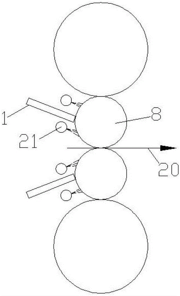
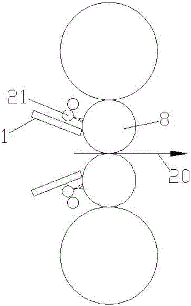
[0073] This embodiment provides a method for wiping and spraying oil on hot rolling work rolls, which specifically includes the following steps:

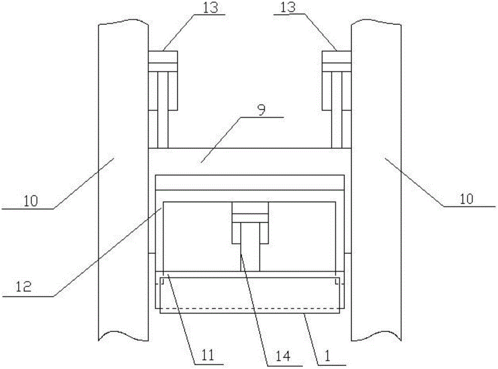
[0074] Step 1. Provide the various components of the above-mentioned wiper oil injection system, and assemble the support frame 9, the first hydraulic cylinder 13, the second hydraulic cylinder 14, the guide mechanism and the wiper blade 1; wherein the wiper oil injection system The structure parameters are as follows:

[0075] The thickness of the wiper 1 is 200mm; the angle β between the chamfered surface 4 and the upper surface of the wiper 1 is 50°; the thickness of the wear-resistant material 5 is 4mm; the height of the groove 7 is 55mm; the diameter of the through hole 6 is 90mm; the outer diameter of the injection header 2 is 85mm, and the inner...


PUM

PropertyMeasurementUnit
thicknessaaaaaaaaaa
diameteraaaaaaaaaa

Abstract

The invention discloses a hot rolling work roll water scraping fuel injection system which comprises a movable device and a water scraper blade installed on the movable device. The movable device can drive the water scraper blade to move towards the roller face of a working roller. A chamfer is arranged at the head of the water scraper blade. The chamfer is located on the intersection of the upper surface of the water scraper blade and the end face of the head. The chamfer is coated with a wear-resisting material. The chamfer makes contact with the working roller. A through hole which is through in the front-back direction is formed in the head of the water scraper blade. A groove is formed in the radial direction of the through hole. One end of the groove is communicated with the through hole. The other end of the groove is communicated with the outer side of the end face of the head of the water scraper blade. A roller-gap lubricating device is installed inside the through hole and the groove. The hot rolling work roll water scraping fuel injection system has the advantages that the roller-gap lubricating device is arranged inside the water scraper blade, the water scraper blade is cooled constantly by cooling water, collected by the water scraper blade, on the working roller, the water scraper blade is in the low-temperature (lower than 50 DEG C) state all the time, and therefore the roller-gap lubricating device is free from high-temperature radiation of hot rolling strip steel.

Description

technical field [0001] The invention belongs to the technical field of hot rolling, and in particular relates to a system and method for wiping and spraying oil for hot rolling work rolls. Background technique [0002] The use of wiper blades and roll gap lubrication is an essential technical means to ensure the smooth progress of hot rolling production. The wiper blades include inlet wiper blades and outlet wiper blades, whose function is to scrape off the cooling water on the surface of the work rolls, prevent the cooling water of the work rolls from splashing on the high-temperature strip, and ensure the temperature requirements of the hot-rolled strip steel. The roll gap lubrication device (including injection header and nozzle) is arranged on the entrance side of the work roll, and its function is to spray the oil-water mixture on the work roll at the entrance side to reduce the friction coefficient of the roll gap, so as to reduce rolling energy consumption and work R...

Claims


Application Information

Patent Timeline
Patent Type & Authority Applications(China)
IPC IPC(8): B21B27/10
CPCB21B27/10B21B2027/103
Inventor 陈全忠吴有生
Owner WISDRI ENG & RES INC LTD
Why Eureka
Try Eureka