Chamfering device for central hole of crankshaft

A chamfering device and center hole technology, which is applied in the directions of center drilling, transportation and packaging, drilling/drilling equipment, etc., can solve the problems of chamfering, low positioning accuracy, labor and time-consuming, etc., and achieve chamfering High precision and good cooling effect

Inactive Publication Date: 2017-02-22
重庆都成荣锋机械制造有限公司
View PDF0 Cites 0 Cited by
  • Summary
  • Abstract
  • Description
  • Claims
  • Application Information

AI Technical Summary

Problems solved by technology

[0002] In the prior art, the chamfering of the center hole of the crankshaft shaft end is completed by an ordinary drilling machine. When chamfering, the crankshaft is first clamped with a clamp, and then the chamfering bit is moved downwards. After the chamfering bit moves in place, the chamfering is performed. The positioning accuracy of the chamfering method is not high, and it is easy to cause chamfering. In addition, due to the high strength and hardness of the crankshaft, the chamfering drill needs to use special cooling oil. The existing cooling oil oiling method is all through manual brushes. Apply it on the drill bit, and apply it once for each chamfer, which is labor-intensive and time-consuming

Method used


Image

  • Chamfering device for central hole of crankshaft

Examples


Embodiment Construction

[0011] The present invention will be further described below in conjunction with the accompanying drawings and specific embodiments, so that those skilled in the art can better understand the present invention and implement it, but the examples given are not intended to limit the present invention.

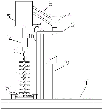
[0012] As shown in the figure, a crankshaft center hole chamfering device includes a chamfering workbench 1 on which a crankshaft chuck 2 and a chamfering device 3 are arranged, and the chamfering device includes a chamfering drill bit 3 , a drill chuck 4 and a driver 5, the chamfering workbench is also provided with a driver bracket, the driver bracket includes a support frame 6 and a rotating shaft 7 arranged on the support frame, and a connection is provided between the rotating shaft and the driver rod 8, the chamfering table is also provided with a cooling oil supply column 9, and the height of the cooling oil supply column is the same as that of the crankshaft.

[0013] When...


PUM


Abstract

The invention discloses a chamfering device for a central hole of a crankshaft. The chamfering device comprises a chamfering workbench, wherein a crankshaft clamping plate and a chamfering instrument are arranged on the chamfering workbench; the chamfering instrument comprises a chamfering drill bit, a drill chuck and a driver; a driver bracket is arranged on the chamfering workbench; the driver bracket comprises a support frame and a rotating shaft arranged on the support frame; a connecting rod is arranged between the rotating shaft and the driver; a cooling oil supply column is arranged on the chamfering workbench; the height of the cooling oil supply column is as same as that of the crankshaft. The chamfering device provided by the invention can quickly and effectively complete the chamfering tasks for the central holes in the two ends of the crankshaft. The chamfering device is higher in chamfering precision and excellent in cooling effect.

Description

technical field [0001] The invention relates to a chamfering device, in particular to a chamfering device for a crankshaft center hole. Background technique [0002] In the prior art, the chamfering of the center hole of the crankshaft shaft end is completed by an ordinary drilling machine. When chamfering, the crankshaft is first clamped with a clamp, and then the chamfering bit is moved downwards. After the chamfering bit moves in place, the chamfering is performed. The positioning accuracy of the chamfering method is not high, and it is easy to cause chamfering. In addition, due to the high strength and hardness of the crankshaft, the chamfering drill needs to use special cooling oil. The existing cooling oil oiling method is all through manual brushes. Apply it on the drill bit, and apply it once for each chamfer, which is labor-intensive and time-consuming. Contents of the invention [0003] In view of this, the object of the present invention is to provide a cranksh...

Claims


Application Information

Patent Timeline
Patent Type & Authority Applications(China)
IPC IPC(8): B23B51/10B23B51/00
CPCB23B51/103B23B51/0063
Inventor 惠高荣曾品利
Owner 重庆都成荣锋机械制造有限公司
Why Eureka
Try Eureka