Improved type in-mold chamfering machine

A chamfering machine and improved technology, which is applied in the field of improved in-mold chamfering machines, can solve the problems of cutting depth not reaching the design data, cutting resistance becomes larger, and achieve simple structure, improved chamfering accuracy, and reasonable design Effect

Pending Publication Date: 2018-02-16
DONGGUAN FOUROCEAN MACHINERY TOOLS
View PDF0 Cites 0 Cited by
  • Summary
  • Abstract
  • Description
  • Claims
  • Application Information

AI Technical Summary

Problems solved by technology

However, due to the limitation of the space structure, the added spring cannot be too large or too high, which will result in insufficient force of the spring and cause the cutting resistance to increase when the tool is worn a little. The moving block is reversed and the cutting depth cannot reach the designed data

Method used


Image

  • Improved type in-mold chamfering machine
  • Improved type in-mold chamfering machine
  • Improved type in-mold chamfering machine

Examples


Embodiment

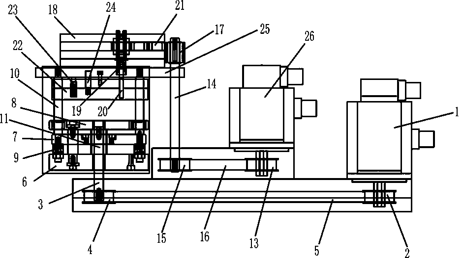
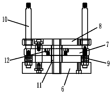
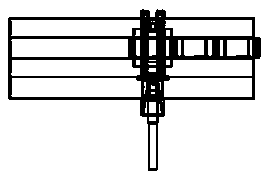
[0013] Such as Figure 1-3 As shown, the present invention includes a rotary drive assembly, a feed drive assembly, a moving block feeding device, and a tool fixing assembly. The rotating drive assembly is connected and matched with the tool fixing assembly; the tool fixing assembly is connected and matched with the moving block feeding device; The feeding device of the moving block is connected and matched with the feeding driving assembly; the feeding driving assembly includes the feeding driving motor 1 with brake function, the first synchronous wheel 2 installed on the main shaft of the feeding driving motor 1, inserted into the moving block feeding The feed connection shaft 3 in the device, the second synchronous wheel 4 sleeved on the feed connection shaft 3, the first synchronous belt 5 sleeved between the first synchronous wheel 2 and the second synchronous wheel 4 for transmission; The moving block feeding device includes a base plate 6, a moving plate 7, an upper pla...


PUM


Abstract

The invention discloses an improved in-mold chamfering machine, which includes a rotary drive assembly, a feed drive assembly, a moving block feed device, a tool fixing assembly, and the rotation drive assembly is connected and matched with the tool fixing assembly; the tool fixing assembly It is connected and cooperated with the moving block feeding device; the moving block feeding device is connected and cooperated with the feed drive assembly; the feed drive assembly includes a feed drive motor with a brake function, a first synchronous wheel installed on the main shaft of the feed drive motor, The feeding connecting shaft inserted into the moving block feeding device, the second synchronous wheel sleeved on the feeding connecting shaft, and the first synchronous belt used for transmission are sleeved between the first synchronous wheel and the second synchronous wheel. The invention is simple in structure and reasonable in design, and can solve the deficiencies of the traditional in-mold chamfering machine in the precision control of the feeding amount and the rigidity. Since two independent servo drive mechanisms are used, and the conveyor belt is used to replace most of the gear components, it can effectively improve Chamfering accuracy.

Description

technical field [0001] The invention relates to an in-mold chamfering machine, in particular to an improved in-mold chamfering machine which can accurately complete feed cutting. Background technique [0002] The in-mold chamfering machine is a commonly used in-mold chamfering device. The existing in-mold chamfering machine has too many transmission gears, and there is a certain transmission gap between the transmission gears, resulting in unstable feeding of the chamfering machine. It is necessary to compulsorily set the feed data to be more than the actual data, and limit the position of the tool by the limit block. In the actual application process, in order to avoid the problem of locking between the moving block and the limit block due to the mandatory limitation of the tool position by the limit block, a spring protection is added to the main shaft of the moving block to prevent the lock of the moving block and the limit block . However, due to the limitation of the ...

Claims


Application Information

Patent Timeline
Patent Type & Authority Applications(China)
IPC IPC(8): B23D79/00
CPCB23D79/00
Inventor 黄剑辉郑镇坚
Owner DONGGUAN FOUROCEAN MACHINERY TOOLS
Why Eureka
Try Eureka