Glass plate perforating device

A punching device and plate technology, applied in the direction of stone processing tools, stone processing equipment, manufacturing tools, etc., can solve the problems of low punching efficiency, affecting punching stability, and clamping parts stuck on the support arm, etc., to achieve High efficiency, stable stamping process, avoiding stuck effect

Active Publication Date: 2017-02-22
重庆市笙建玻璃有限公司
View PDF5 Cites 4 Cited by
  • Summary
  • Abstract
  • Description
  • Claims
  • Application Information

AI Technical Summary

Problems solved by technology

However, the above-mentioned technical solution has the following defects: 1. In the process of processing, the punch needs to be rotated at 180°C, and then punched in turn, which makes the punching efficiency low and affects the processing speed; 2. The two ends of the clamping parts on the support arm are respectively Connected to the support arm, each of the two ends of the clamping piece is pushed by a push cylinder. Since the pushing process of the two push cylinders cannot be completely consistent, the speed of the two ends of the clamping piece cannot be completely consistent, which is very easy to cause the clamping The fastener is stuck on the support arm, which affects the stability of stamping

Method used


Image

  • Glass plate perforating device
  • Glass plate perforating device
  • Glass plate perforating device

Examples


Embodiment Construction

[0018] The present invention will be further described in detail below through specific implementations:

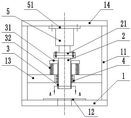
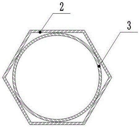
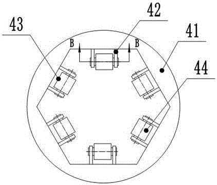
[0019] The reference signs in the drawings of the specification include: base 1, support arm 11, working platform 12, middle beam 13, upper beam 14, round punch 2, flange 21, hexagonal punch 3, mounting plate 31, The spring 32, the sliding sleeve 4, the sleeve 41, the mounting frame 42, the belt 43, the pulley 44, the pushing cylinder 5, and the connecting plate 51.

[0020] The embodiment is basically as attached figure 1 And figure 2 Shown:

[0021] The glass sheet punching device in this solution includes a support, and the support includes a work platform 12 on which stamping parts are placed. The two sides of the work platform 12 are welded with longitudinal support arms 11, and the two support arms 11 are transversely A middle beam 13 is connected, a through hole is machined on the middle beam 13, a sliding sleeve 4 is installed in the through hole, and a punch is instal...


PUM


Abstract

The invention relates to a perforating device, and discloses a glass plate perforating device. The glass plate perforating device comprises a support. The support comprises a working platform for containing pieces to be punched. Longitudinal supporting arms are arranged on the two sides of the working platform. A middle cross beam is transversely connected between the two supporting arms and provided with a through hole. A sliding sleeve is mounted in the through hole, and a puncher pin is arranged in the sliding sleeve in a matched manner and comprises an inner round puncher pin body and a hexagonal puncher pin body. The inner round puncher pin body is sleeved with the hexagonal puncher pin body and is internally tangent to the hexagonal puncher pin body. The upper end of the hexagonal puncher pin body is connected with a mounting plate, and springs are connected between the mounting plate and the middle cross beam. According to the technical scheme, in the machining process, a pushing air cylinder moves continuously downwards and cannot stop in the middle, and therefore the efficiency of the punching process is higher; and the pushing air cylinder directly drives the puncher pin to carry out punching, the puncher pin is matched in the sliding sleeve mounted on the cross beam and cannot deflect in the advancing process, and therefore the punching process is more stable, and clamping is avoided.

Description

Technical field [0001] The invention relates to a punching device. Background technique [0002] In the field of machining, it is usually necessary to machine special-shaped holes on the workpiece, among which the hexagonal hole is the most common hole type. The existing hexagonal hole processing is to directly use the hexagonal punch to hedge the workpiece to form a hexagonal hole on the workpiece . This processing method is to use the hexagonal punch to flush the material on the workpiece that needs to be punched away from the workpiece. When the hexagonal punch acts on the workpiece, the material at the contact point of the hexagonal punch and the workpiece is affected by the impact force. It is squeezed and deformed and then separated from the workpiece. This kind of punching is easy to produce burrs on the edge of the hexagonal hole on the workpiece. After processing, the workpiece needs to be ground, which is time-consuming and labor-intensive and increases the processing ...

Claims


Application Information

Patent Timeline
Patent Type & Authority Applications(China)
IPC IPC(8): B28D1/14
CPCB28D1/14B28D1/146
Inventor 刘德燕
Owner 重庆市笙建玻璃有限公司
Why Eureka
Try Eureka