A railway auxiliary vacuum automatic grouting machine

An all-in-one, automatic technology, which is applied in the erection/assembly of bridges, bridges, buildings, etc., can solve the problems of unrealized automatic control, impact on construction quality, and large impact of manual intervention, so as to improve the degree of automatic operation and control, and ensure the weighing The effect of measuring accuracy and weighing accuracy is not reduced

Active Publication Date: 2018-04-20
RAILWAY ENG RES INST CHINA ACADEMY OF RAILWAY SCI +2
View PDF11 Cites 0 Cited by
  • Summary
  • Abstract
  • Description
  • Claims
  • Application Information

AI Technical Summary

Problems solved by technology

The currently commonly used grouting trolley lacks an automatic feeding weighing system or has defects such as inaccurate feeding and weighing, arbitrary slurry configuration, and long powder transmission stroke; the integration of equipment at both ends of the pipeline is not high, and manual intervention affects The degree of automation of the grouting operation is limited, resulting in complex grouting operations, unstable grouting process, easy residual air at the grouting end, resulting in unsatisfactory construction, and serious construction dust pollution, etc., specifically manifested in:
[0003] (1) The traditional method in railway grouting is to rely on screw auger or manual feeding method, which has serious problems such as dust pollution
[0004] (2) Due to construction needs, the current vacuum equipment and grouting pumps are placed at both ends of the beam body respectively, and are controlled manually and by the system respectively. The degree of automation is low, and the process conversion and operation are difficult to control, which affects the construction quality
[0005] (3) In the prestressed pipeline grouting operation, the slurry needs to be weighed and prepared according to the formula requirements. It is required that the weighing error of water and powder should be controlled within ±1%. Feeding and weighing in the stirring state of the high-speed mixing tank, especially for the slurry controlled by multiple metering, there is a large error, which directly affects the quality of the slurry
[0006] (4) Grouting pump is an important equipment for grouting operations of prestressed pipelines. Currently, the commonly used continuous grouting pump—screw pump is easy to burn out the stator when it is running without slurry. Even if it is carefully maintained, 80-100 pieces of boxes are used. The rotor and stator must also be replaced when the beam is grouted, and the life cycle of the whole process is short. In addition, the currently used screw pump cannot record the amount of grouting slurry
The process does not realize the automatic control of the whole process, and the operation is relatively complicated. If the control is not proper, there will be accidents where the slurry is sucked into the vacuum pump and damaged; at the same time, there is no vent hole at the press end, which may easily cause voids and insufficiency near the slurry inlet. ;Pipeline grouting should be carried out as soon as possible after tensioning. The grouting should be carried out slowly, evenly and continuously. In order to ensure the quality of grouting, it is necessary to vacuumize the grouting. The slurry is separated separately. After the vacuuming is completed, the grouting pipeline needs to be reconnected. The process is cumbersome and the operation is complicated.

Method used


Image

  • A railway auxiliary vacuum automatic grouting machine
  • A railway auxiliary vacuum automatic grouting machine
  • A railway auxiliary vacuum automatic grouting machine

Examples


Embodiment 1

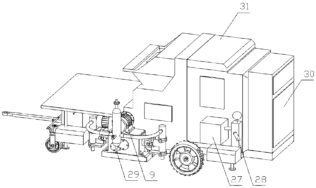
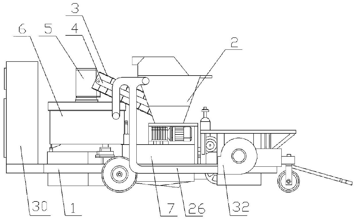
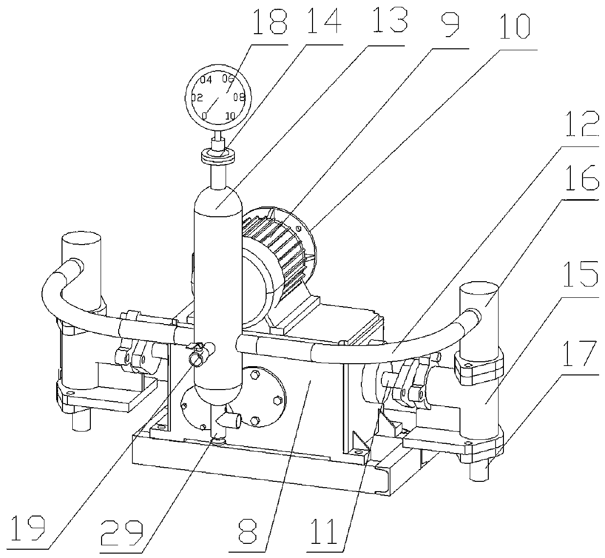
[0044] Such as Figure 6 As shown, the grouting end of the pipeline of the prestressed concrete beam is also provided with an air release pipe 33 . The slurry outlet end of the pipeline of the prestressed concrete beam is provided with a slurry outlet pipe 34 . The vacuum pipe 28, the air release pipe 33, and the grout outlet 29 are all sealed and connected to the pipes of the prestressed concrete beam, and the pipes are respectively provided with corresponding valves. The vacuuming and grouting process of embodiment one are as follows: check the valve situation of the pipeline of the prestressed concrete beam, ensure that the grouting outlet 29, the vacuum pipe 28, the air release pipe 33, and the grouting pipe 34 are all tightly connected with the pipeline, Form a sealed state, and the initial state of each valve is closed; open the valve of the vacuum tube 28 and start the vacuum pump 27 through the PLC assembly electric control box 30, and vacuumize the pipeline. When the...

Embodiment 2

[0046] Such as Figure 7 As shown, the slurry outlet end of the pipeline of the prestressed concrete beam is provided with a slurry outlet pipe 34 . The vacuum pipe 28 and the grout outlet 29 are both sealed and connected to the pipes of the prestressed concrete beams, and the pipes are respectively provided with corresponding valves. The vacuuming and grouting process of embodiment two are as follows: check the valve situation of the pipeline of the prestressed concrete beam, ensure that the grouting outlet 29, the vacuum pipe 28, the air release pipe 33, and the grouting pipe 34 are all tightly connected with the pipeline, Form a sealed state, and the initial state of each valve is closed; open the valve of the vacuum tube 28 and start the vacuum pump 27 through the PLC assembly electric control box 30, and vacuumize the pipeline. When the vacuum in the pipeline is stable at the standard technical requirements When within the range, close the valve of the vacuum tube 28, di...


PUM


Abstract

The invention discloses an auxiliary vacuumizing and automatic mud jacking integrated machine for railways. The auxiliary vacuumizing and automatic mud jacking integrated machine for railways comprises a rack, an automatic mud jacking system and a vacuumizing system, wherein the automatic mud jacking system and the vacuumizing system are arranged on the rack. The automatic mud jacking system comprises a feeding system, a high-speed and low-speed stirring system, a static weighing system, a mud jacking and pressure stabilizing system, an environmental protection dust removal system, an automatic control system, a data storage and transmission system, an equipment self-inspection system, a cleaning system and an alarm system. By means of the novel vacuumizing and automatic mud jacking integrated machine, the purpose of conducting vacuumizing and mud jacking work at the same end of a pipeline is achieved, one-key operation of the work is achieved by adopting the uniform central control system, operation control is simplified, the automatic operation and control degree of the vacuumizing and mud jacking work are improved, accurate feeding and weighing, stable and continuous mud jacking and controllable flow are achieved, plumpness of mud in the pipeline can be guaranteed, and the whole construction process is environmentally friendly and free of pollution.

Description

technical field [0001] The invention belongs to the field of railway machinery, and in particular relates to a railway auxiliary vacuum automatic grouting integrated machine. Background technique [0002] Railway grouting machines are mainly used for grouting prestressed pipelines in bridges. Pipeline grouting is one of the most important construction links in post-tensioned beams. At present, vacuum-assisted grouting technology is basically used. The currently commonly used grouting trolley lacks an automatic feeding weighing system or has defects such as inaccurate feeding and weighing, arbitrary slurry configuration, and long powder transmission stroke; the integration of equipment at both ends of the pipeline is not high, and manual intervention affects The degree of automation of the grouting operation is limited, resulting in complex grouting operations, unstable grouting process, easy residual air at the grouting end, resulting in unsatisfactory construction, and seri...

Claims


Application Information

Patent Timeline
Patent Type & Authority Patents(China)
IPC IPC(8): E01D21/00
CPCE01D21/00
Inventor 马林胡所亭苏永华王乐然张勇崔建军
Owner RAILWAY ENG RES INST CHINA ACADEMY OF RAILWAY SCI
Why Eureka
Try Eureka