
Novel liquid air energy storage system using phase change energy storage

A liquid air and energy storage system technology, applied in the direction of liquefaction, refrigeration and liquefaction, heat exchanger type, etc., can solve the problems of increased construction costs, low energy storage density of compressed air energy storage technology, etc., to improve heat storage efficiency and improve Effect of cooling storage efficiency and efficiency improvement

Inactive Publication Date: 2017-02-22
NANJING UNIV OF TECH
View PDF8 Cites 19 Cited by
  • Summary
  • Abstract
  • Description
  • Claims
  • Application Information

AI Technical Summary

Problems solved by technology

However, the energy storage density of compressed air energy storage technology is low, and the difficulty lies in the need for a suitable place to store compressed air. The underground salt cavern is the lowest-cost gas storage room in the compressed air energy storage system, and the salt cavern still needs to have sufficient depth. Underwater CAES is also being studied, but also requires a suitable water depth
If a large number of air storage tanks are used on the ground to store compressed high-pressure air, the construction cost will be greatly increased

Method used


Image

  • Novel liquid air energy storage system using phase change energy storage
  • Novel liquid air energy storage system using phase change energy storage
  • Novel liquid air energy storage system using phase change energy storage

Examples


Embodiment Construction

[0025] The present invention is described in further detail now in conjunction with accompanying drawing.

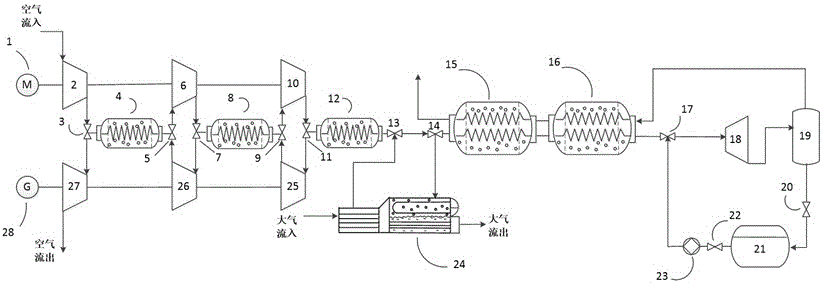
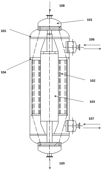
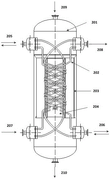
[0026] like figure 1 The new liquid air energy storage system using phase change energy storage shown includes a drive unit 1, a compressor group, a heat accumulator group, cold storage devices 15, 16, a liquid expander 18, a gas-liquid separator 19, and a liquid air storage tank 21. Cryopump 23, vaporizer 24, main expansion unit and generator 28. Wherein, the compressor unit includes multiple compressors 2, 6, 10 connected in series, the main expansion unit includes multiple main expanders 25, 26, 27 connected in series, and the heat accumulator group includes multiple heat accumulators 4, 8, 12, The number of compressors 2, 6, 10, main expanders 25, 26, 27 and heat accumulators 4, 8, 12 are the same and correspond to each other, and the compressors 2, 6, 10 and heat accumulators 4, 8, 12 are sequentially spaced connection, the main expanders 25, 26, 27 and the regene...


PUM


Abstract

The invention relates to a novel liquid air energy storage system using phase change energy storage. The novel liquid air energy storage system has two working states including energy storage and energy releasing; in the energy storage process, a compressor unit is driven by a driving unit, and is sequentially connected with a heat accumulator set, a regenerator, a liquid expansion machine, a gas-liquid separator and a liquid air storage tank; and in the energy releasing process, a cryogenic pump is sequentially connected with the regenerator, a vaporizer, the heat accumulator set and a main expansion machine set, the main expansion machine set drives a power generator, the cryogenic pump is connected with the liquid air storage tank, winding pipe type heat exchangers are adopted in the heat accumulator set and the regenerator, a phase change heat storage material is contained in a shell pass, and an intermediate medium vaporizer is adopted as the vaporizer. According to the novel liquid air energy storage system, the winding pipe type heat exchangers and the intermediate medium vaporizer are applied to the liquid air energy storage system, air is led into a pipe pass to exchange heat with the phase change heat storage material and a phase change cold storage material in the shell side, compressed heat and liquid air cold are stored by the phase change heat storage material and the phase change cold storage material correspondingly, circulated utilization of the heat and the cold is guaranteed, and the efficiency of the system is improved.

Description

technical field [0001] The invention belongs to the field of energy storage, and in particular relates to a novel liquid air energy storage system utilizing phase change energy storage. Background technique [0002] In today's world, the demand for energy continues to increase, and the excessive dependence on fossil fuels will lead to serious environmental and climate problems. The development of new renewable energy and the improvement of the utilization rate of existing energy have become a topic of concern to scholars and scientists around the world. Wind energy and solar energy are the most competitive forms of new energy in terms of technology and cost, but they have intermittent and unstable power generation characteristics, so they must rely on energy storage technology to store their energy to improve their power output quality and increase power generation. economy and reliability. Existing electric energy storage technologies include pumped water storage, compress...

Claims


Application Information

Patent Timeline
IPC IPC(8): F01D15/10F25J1/02F28D20/02
CPCF01D15/10F25J1/0228F25J1/0235F28D20/02F25J1/0012F25J1/004F25J1/0042F25J1/0045F25J1/0202F25J1/0242F25J1/0251F25J1/0263F25J2205/24F25J2230/04F25J2230/30F25J2235/02F25J2240/90Y02E60/14
Inventor 凌祥杨谕彭浩
Owner NANJING UNIV OF TECH
Learn More