
Control apparatus for power transmission system

A power transmission and control device technology, which is applied in the direction of multi-ratio transmission, transmission, transmission control, etc., can solve the problems of drivability deterioration and achieve the effect of reducing the deterioration of drivability and reducing noise

Inactive Publication Date: 2017-02-22
TOYOTA JIDOSHA KK
View PDF5 Cites 6 Cited by
  • Summary
  • Abstract
  • Description
  • Claims
  • Application Information

AI Technical Summary

Problems solved by technology

In this case, since the load acts in the direction of reducing the rotational speed of the input shaft of the automatic transmission, that is, because the torque is internally circulated, drivability may deteriorate
That is, if the semi-interlock state is always established in order to reduce vehicle vibration or noise, drivability may deteriorate

Method used


Image

  • Control apparatus for power transmission system
  • Control apparatus for power transmission system
  • Control apparatus for power transmission system

Examples


Embodiment Construction

[0026]Hereinafter, embodiments of the present invention will be described in detail with reference to the accompanying drawings.

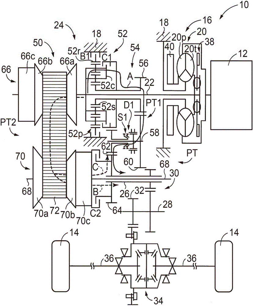
[0027] figure 1 is a view showing a schematic configuration of a vehicle 10 to which the first embodiment of the present invention is applied. exist figure 1 In the vehicle 10 includes an engine 12 , drive wheels 14 and a powertrain 16 . The engine 12 is a gasoline engine, a diesel engine, or the like used as a driving force source for propelling the vehicle 10 . A power transmission system 16 is provided in a power transmission path between the engine 12 and the drive wheels 14 . The power transmission system 16 includes a torque converter 20 , an input shaft 22 , an automatic transmission 24 , an output shaft 26 , a counter shaft 28 , a reduction gear unit 30 , a differential gear set 34 , a pair of axle shafts 36 , and the like. The input shaft 22 is coupled to the torque converter 20 . An automatic transmission 24 is coupled to input shaft...


PUM


Abstract

When a state of a vehicle is a predetermined state of the vehicle where vehicle vibration occurs, weak circulating torque is generated to fill backlash inside an automatic transmission and in a power transmission path by half-engaging a second clutch for establishing a second power transmission path while a first power transmission path remains established in the automatic transmission. A speed ratio of the second power transmission path is alternatively set to a lower vehicle speed-side speed ratio with respect to a speed ratio of the first power transmission path or a higher vehicle speed-side speed ratio with respect to the speed ratio of the first power transmission path in response to a traveling state. It is possible to generate weak circulating torque in a direction to increase an input shaft rotation speed or in a direction to reduce the input shaft rotation speed in accordance with the traveling state.

Description

technical field [0001] The present invention relates to a control device for a power transmission system including an automatic transmission capable of providing different power transmission paths for transmitting power of a driving power source to driving wheels. Background technique [0002] There is known a control device for a power transmission system including an automatic transmission in which a first power transmission path and a second power transmission path for transmitting power from a driving power source to drive wheels are selectively established. One. In a predetermined state of the vehicle in which vehicle vibration occurs, the control device reduces vehicle vibration or noise generated by vehicle vibration by half-engaging the engagement device for establishing the second power transmission path while maintaining establishment of the first transmission path. This is, for example, a vibration damping system for a vehicle described in Japanese Patent Applica...

Claims


Application Information

Patent Timeline
Patent Type & Authority Applications(China)
IPC IPC(8): F16H61/02F16H59/16F16H59/68F16H61/688
CPCF16H59/16F16H59/68F16H61/0206F16H61/0213F16H61/688F16H61/0204F16H61/66259B60Y2300/20F16H2037/026F16H3/663F16H57/0006F16H2200/0052F16H2200/2007F16H2200/2043F16H2200/2066F16H2200/2082F16H2057/0012F16H37/022F16H2702/02F16H2702/06B60W30/20F16H61/662F16H61/702F16H37/021
Inventor 中村和明
Owner TOYOTA JIDOSHA KK
Learn More