
Paving device and paving system for flexible liquid supply pipes

A technology for laying devices and liquid supply pipes, which is applied in the directions of pipeline laying and maintenance, pipeline supports, mechanical equipment, etc., can solve the problems of low convenience of flexible liquid supply pipes, large supporting force exerted by water belts, and high energy consumption

Inactive Publication Date: 2017-02-22
北京金雨龙机器人科技发展有限责任公司
View PDF6 Cites 4 Cited by
  • Summary
  • Abstract
  • Description
  • Claims
  • Application Information

AI Technical Summary

Problems solved by technology

However, in practical applications, since the hose has its own weight, when the distance between the water source and the fire location is relatively long, there is a problem of excessive traction caused by the overweight of the hose during the laying of the hose. The belt cannot be easily laid and pulled to the fire position, resulting in low laying convenience; at the same time, in order to complete the operation of laying the hose, it is necessary to apply a large supporting force to the hose, which leads to the consumption of laying the hose. big energy
[0005] Through the above discussion, the defects of low convenience and high energy consumption in the laying process of flexible liquid supply pipes in the prior art are technical problems that need to be solved by those skilled in the art.

Method used


Image

  • Paving device and paving system for flexible liquid supply pipes
  • Paving device and paving system for flexible liquid supply pipes
  • Paving device and paving system for flexible liquid supply pipes

Examples


Embodiment Construction

[0035] The core of the present invention is to provide a laying device and a laying system for a flexible liquid supply pipe. Through the application of the present invention, the convenience in laying the flexible liquid supply pipe can be significantly improved, and energy consumption can be reduced at the same time.

[0036] The following will clearly and completely describe the technical solutions in the embodiments of the present invention with reference to the accompanying drawings in the embodiments of the present invention. Obviously, the described embodiments are only some, not all, embodiments of the present invention. Based on the embodiments of the present invention, all other embodiments obtained by persons of ordinary skill in the art without making creative efforts belong to the protection scope of the present invention.

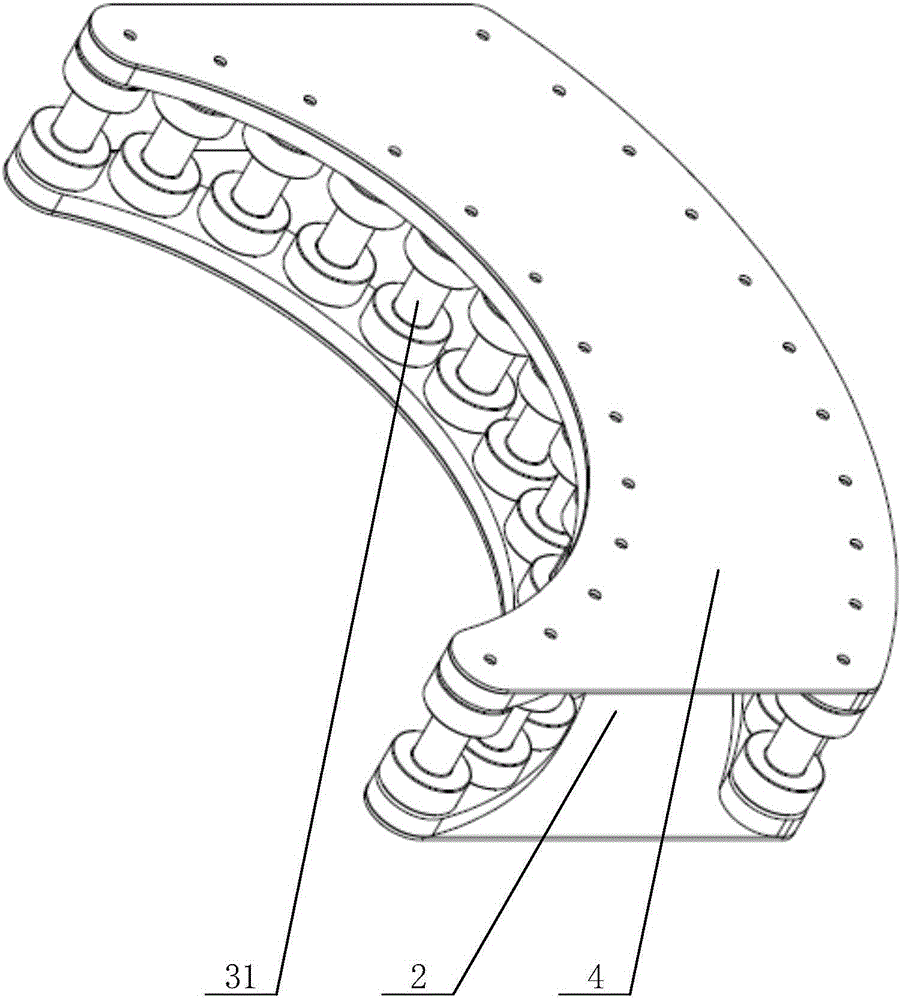
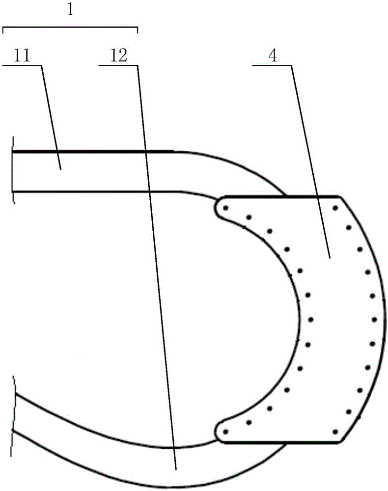
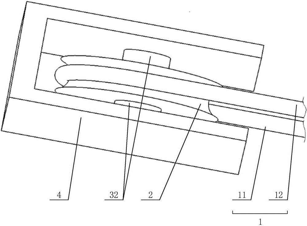
[0037] Please refer to Figure 1 to Figure 7 , figure 1 is a first schematic diagram of a first schematic structure of a laying device; f...


PUM


Abstract

The invention relates to the technical field of control control, in particular to a paving device and a paving system for flexible liquid supply pipes. The paving device comprises a moving part and a guide part mounted as a whole; the guide part includes an arc through groove embedded in the flexible liquid supply pipes; the moving part is butted against a bearing basal body for bearing the paving device, and can move corresponding to the bearing basal body; the flexible liquid supply pipes include extension sections for penetrating through the arc through groove, and followup sections not penetrating through the arc through groove; the extension sections and the followup sections are respectively positioned on two sides of the arc through groove; the paving device can flatly move; and the flat moving direction is corresponding to the moving direction of the extension sections. The structure is set by the structure principle of a movable pulley, so that the dragging convenience for the flexible liquid supply pipes is prominently improved, and the dragging energy consumption is reduced. The invention further provides a paving system; the paving system comprises two paving devices oppositely arranged for realizing setting and dragging of the flexible liquid supply pipes in the same one direction; and meanwhile, the paving system improves the dragging convenience, and reduces the energy consumption.

Description

technical field [0001] The invention relates to the technical field of fire protection, in particular to a laying device and a laying system for flexible liquid supply pipes. Background technique [0002] With the development of society, various equipments are used in the field of fire fighting, among which, flexible liquid supply pipes are usually required in the process of draining liquid fire extinguishing media. [0003] At present, the requirements for the convenience of flexible liquid supply pipes in the laying process and the reduction of energy consumption are getting higher and higher. Therefore, improving the convenience of flexible liquid supply pipes in the laying process and reducing energy consumption have become the field Technologist's design goals. [0004] In the prior art, in the field of firefighting, when it is necessary to put out and rescue a fire location, it is usually necessary to lay flexible liquid supply pipes, and then drain the liquid fire ex...

Claims


Application Information

Patent Timeline
IPC IPC(8): F16L1/024F16L1/06F16L3/015A62C33/00
CPCF16L1/0246A62C33/00F16L1/06F16L3/015
Inventor 谢洪德董占红曹道阳张鹏郑仲
Owner 北京金雨龙机器人科技发展有限责任公司
Learn More