Calcining equipment

A calcination and equipment technology, applied in the field of calcination equipment, can solve the problems of low thermal conductivity, cumbersome, uneven heating of particles, etc.

Active Publication Date: 2017-02-22
DEMETER SUZHOU ELECTRONICS ENVIRONMENTAL MATERIALS CO LTD
View PDF7 Cites 1 Cited by
  • Summary
  • Abstract
  • Description
  • Claims
  • Application Information

AI Technical Summary

Problems solved by technology

However, since the flame directly contacts and burns the particles in the annular combustion chamber, it is easy to locally heat the particles around the flame, resulting in excessive combustion of the particles
Moreover, due to the

Method used


Image

  • Calcining equipment
  • Calcining equipment
  • Calcining equipment

Examples


Embodiment Construction

[0020] In order to make the above objects, features and advantages of the present invention more comprehensible, specific implementations of the present invention will be described in detail below in conjunction with the accompanying drawings. In the following description, numerous specific details are set forth in order to provide a thorough understanding of the present invention. However, the present invention can be implemented in many other ways different from those described here, and those skilled in the art can make similar improvements without departing from the connotation of the present invention, so the present invention is not limited by the specific implementations disclosed below.

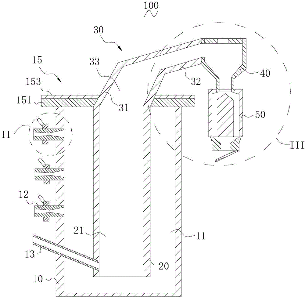
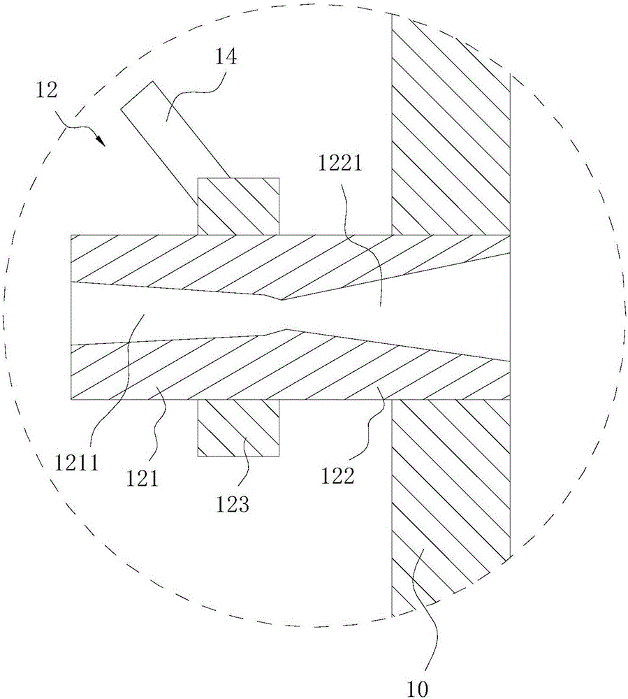
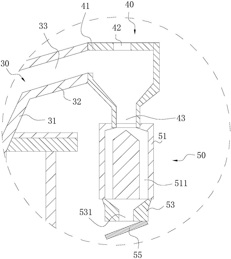
[0021] The invention relates to a calcining equipment. The calcining equipment includes a combustion cylinder, a calcining cylinder, a discharge pipe, a solid-liquid separation cylinder, and a discharge member. A furnace is formed inside the calcining cylinder, and the combustion cyli...


PUM


Abstract

The invention relates to calcining equipment. The calcining equipment comprises a combustion barrel, a calcining barrel, a discharge pipe, a solid-liquid separation barrel and an unloading part. A hearth is formed in the calcining barrel, the calcining barrel is sleeved with the combustion barrel, and an annular combustion chamber is formed between the combustion barrel and the calcining barrel. A feed pipe and multiple combustion nozzles are arranged on the combustion barrel, the solid-liquid separation barrel is arranged at the end of the discharge pipe, and the unloading part is arranged on the solid-liquid separation barrel. The extension direction of the combustion nozzles is vertical to that of the combustion barrel, combustion supporting air pipes are arranged on the combustion nozzles and inclined relative to the combustion nozzles, and each combustion nozzle comprises a guiding part and a connecting part connected with the guiding part. The calcining equipment can avoid excessive combustion, and is high in heat conducting efficiency, and fuel can be conveniently guided in.

Description

technical field [0001] The invention relates to a calcining equipment. Background technique [0002] A calciner is a piece of equipment used for high-temperature processing, such as in ironmaking, recycling rare metals, producing catalysts or calcining pellets. Calciners are generally used for processing small particle materials, for example, materials that are sensitive to oxidation, combustion, explosion and heat. The furnace body of the calcination equipment is provided with a combustion chamber, and the particles to be calcined are accommodated in the annular combustion chamber and calcined in the annular combustion chamber. However, since the flame directly contacts and burns the particles in the annular combustion chamber, the particles around the flame are easily heated locally, resulting in excessive combustion of the particles. Moreover, due to the blocking of the particles adjacent to the flame, the remaining particles are heated unevenly, and the heat conduction...

Claims


Application Information

Patent Timeline
IPC IPC(8): F27B15/00F27B15/02
CPCF27B15/00F27B15/02
Inventor 周利虎刘宇杰宋军
Owner DEMETER SUZHOU ELECTRONICS ENVIRONMENTAL MATERIALS CO LTD
Why Eureka
Try Eureka