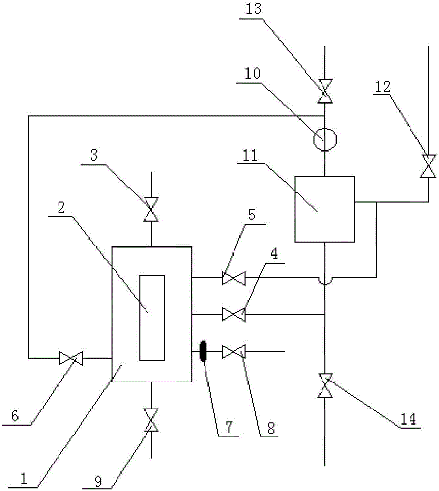
Rubber ball cleaning system with ball recycling and counting device

A technology of counting device and cleaning system, which is applied in the field of rubber ball cleaning system with ball collection and counting device, can solve the problems of high equipment investment cost, easy leakage of rubber seal, cumbersome operation steps, etc., so as to reduce workload and prevent damage Leakage, simple effect of the system

Pending Publication Date: 2017-02-22
DATANG QINGYUAN THERMOELECTRICITY
View PDF0 Cites 2 Cited by
  • Summary
  • Abstract
  • Description
  • Claims
  • Application Information

AI Technical Summary

Problems solved by technology

There are also some newly-built power plants that have adopted more advanced rubber ball cleaning devices, which can count rubber balls through special devices, but the investment cost of equipment is very high. Generally, the rubber ball system of power plants operates normally, and will not invest a lot of money in equipment transformation , so it does not change the status quo of heavy workload of operators
[0004] Moreover, there is a ball-filling end cover on the top of the ball-filling room of the condenser rubber-ball cleaning system. After the balls are loaded, the ball-filling system can be operated, but the balls can only be received in the ball-filling room. After counting the number of rubber balls and calculating the ball collection rate, they can only be put into the net bag at the drain through the drain door installed at the outlet pipe of the balling room. After manually counting the balls, isolate the rubber ball cleaning system and open the balling room for balling. After adding the old balls and supplementary new balls, the recovery system will run again. The operation steps are cumbersome and the workload of the personnel is heavy. Repeated operations of adding balls to the ball chamber will cause the rubber seal to leak easily.

Method used


Image

  • Rubber ball cleaning system with ball recycling and counting device

Examples


Embodiment Construction

[0027] The technical solutions in the embodiments of the present invention are clearly and completely described below in conjunction with the accompanying drawings in the embodiments of the present invention. Obviously, the described embodiments are only part of the embodiments of the present invention, not all of them. Based on the embodiments of the present invention, all other embodiments obtained by persons of ordinary skill in the art without making creative efforts belong to the protection scope of the present invention.

[0028] In the following description, a lot of specific details are set forth in order to fully understand the present invention, but the present invention can also be implemented in other ways different from those described here, and those skilled in the art can do it without departing from the meaning of the present invention. By analogy, the present invention is therefore not limited to the specific examples disclosed below.

[0029] Such as figure ...


PUM


Abstract

The invention discloses a rubber ball cleaning system with a ball recycling and counting device. The rubber ball cleaning system comprises a water tank, an observation window, a valve and a pipeline. The water tank, the valve and the pipeline are connected to an original rubber ball cleaning system. Marking scales are arranged on the observation window, an upward gate valve is arranged on the top of the water tank, a ball filling opening can be formed when the gate valve is opened, and opening and closing are convenient. A drainage valve and a filtering net are arranged at the bottom of the water tank, and rubber balls are prevented from being discharged from the position during drainage. One pipeline is connected to a pipeline in front of a ball recycling outlet door of the original rubber ball cleaning system to the upper portion of the water tank, and the lower portion of the water tank is connected with one pipeline to a rubber ball pump inlet pipeline of the original rubber ball cleaning system. After rubber ball counting and new ball filling are finished, a rubber ball pump is started, high-pressure water at a rubber ball pump outlet can be injected through the upper pipeline of the water tank, rubber balls in the water tank are beaten into a low-pressure pipeline of a rubber ball pump inlet from the lower portion, and the rubber balls enter the rubber ball cleaning procedure along with water flow.

Description

technical field [0001] The invention relates to the field of rubber ball cleaning devices for condensers or tubular heat exchangers, in particular to a rubber ball cleaning system for condensers in thermal power plants, which integrates the functions of recycling rubber balls and adding new balls. Rubber ball cleaning system with ball collection and counting device. Background technique [0002] The ball collection rate of the rubber ball system is an important basis for judging whether there are problems such as rubber ball blockage in the condenser, ball leakage due to lax collection nets, and blockage of the ball collection port. Therefore, the ball collection rate should be counted frequently, but the required accuracy Not high, the volume is used to estimate the number of rubber balls, and the deviation does not exceed 100. For the base of 2000 rubber balls, the calculation requirements can be met, and if the balls are counted manually, the accuracy will not be very hig...

Claims


Application Information

Patent Timeline
Patent Type & Authority Applications(China)
IPC IPC(8): F28G1/12F28G15/00
CPCF28G1/12F28G15/00F28G2015/006
Inventor 张赞延峰吕晓华
Owner DATANG QINGYUAN THERMOELECTRICITY
Why Eureka
Try Eureka