
Liquid-filled soil stress test device and test method

A technology of stress testing and stress, applied in measuring devices, force/torque/work measuring instruments, hydraulic/pneumatic force measurement, etc., can solve problems such as inability to test confining pressure, singleness, large deformation and cannot be accurately tested, and achieve Large soil deformation adaptability, the effect of accurate testing

Inactive Publication Date: 2017-02-22
青海省交通科学研究院 +1
View PDF10 Cites 2 Cited by
  • Summary
  • Abstract
  • Description
  • Claims
  • Application Information

AI Technical Summary

Problems solved by technology

Therefore, in flexible subgrades, foundations, high fill and other soils, there are still many defects when using vibrating wire stress gauges to test soil stress changes. For example, the confining pressure cannot be tested due to the singleness of the test direction, Shelling due to contact, unable to accurately test stress change state due to inadaptation to large deformation of soil, etc.

Method used


Image

  • Liquid-filled soil stress test device and test method
  • Liquid-filled soil stress test device and test method
  • Liquid-filled soil stress test device and test method

Examples


Embodiment 1

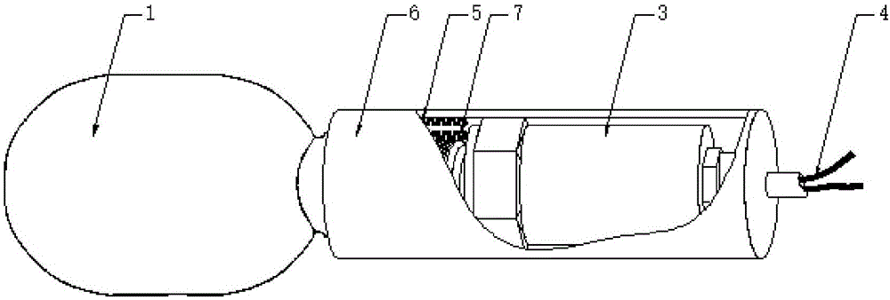
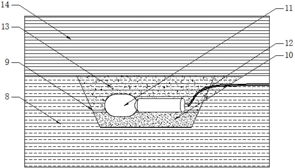
[0024] A liquid bladder soil stress testing device, comprising a bladder stress housing 1, a protection tube 6 and a transmission converter 3:

[0025] The bladder stress shell 1 is filled with a stress transmission medium 2, which is a liquid medium, and the contact surface between the bladder stress shell 1 and the soil is arc-shaped, which effectively solves the problem caused by the contact plane of the existing stress gauge. Unidirectional defects can contact the soil in all directions and fully sense the stress change of the unit soil; at the same time, the capsule stress shell 1 has strong elasticity and ductility, and can change shape with the deformation of the soil, effectively solving the problem. It overcomes the defect that the existing stress gauge is slightly deformed and cannot adapt to the large deformation of the soil, and the shelling phenomenon will not occur during use; the stress transmission medium 2 is in a liquid state, and no stress loss occurs during ...

Embodiment 2

[0027] In this embodiment, the transmission converter 3 is sealed and connected to the capsule stress shell 1 through the transmission converter connecting thread 5 . The remaining technical solutions of this embodiment are consistent with those of Embodiment 1, and the technical solutions adopted in this embodiment are also applicable to other embodiments.

Embodiment 3

[0029] In this embodiment, when the transmission converter 3 is connected to the capsule stress housing 1, it is sealed by a sealant. The remaining technical solutions of this embodiment are consistent with those of Embodiment 2, and the technical solutions adopted in this embodiment are also applicable to other embodiments.


PUM


Abstract

The invention relates to a liquid-filled soil stress test device which comprises a capsule-type stress casing body, a protective tube and a transmitting converter. The capsule-type stress casing body is filled with a stress transmission medium which is a liquid medium. The contact surface of the capsule-type stress casing body and the soil body is arc-shaped. Stress transmitted by the transmission medium directly generates a stress signal through the transmitting converter, and the stress signal is output through a signal cable. The transmitting converter is in sealed connection with the capsule-type stress casing body. The protective tube is arranged on the outer side of the transmitting converter. The signal cable is led out through the open ends of the protective tube, and the other end is in sealed connection with the capsule-type stress casing body. The invention further discloses a test method for the liquid-filled soil stress test device. The test device and the test method have the advantages that contact with the soil body is realized in all directions; the stress change of the unit soil body can be fully sensed; the shape of the device can be changed with the deformation of the soil body; the soil body deformation adaptability is high; and the stress change state can be accurately tested.

Description

technical field [0001] The invention relates to the technical field of soil stress testing, in particular to a liquid bladder type confining pressure soil stress meter. The invention can also be used for the stress test caused by self-weight or load in soil bodies such as roadbeds, foundations, and high fillings. Background technique [0002] Soil stress is an important parameter to reflect the working state of roadbed, foundation, high fill and other soils. The distribution of soil stress not only has the significance of theoretical research and practice, but also has the function of guiding engineering research, design, construction, operation and maintenance, etc. [0003] The commonly used test devices in soil stress testing mainly include vibrating wire stress gauges. The vibrating wire stress gauges are mainly composed of a back plate, an induction plate, a vibrating wire, an excitation electromagnetic coil, and a signal transmission cable. They are planar and unidirec...

Claims


Application Information

Patent Timeline
Patent Type & Authority Applications(China)
IPC IPC(8): G01L5/00G01L1/02
CPCG01L1/02G01L5/0047
Inventor 徐安花米维军房建宏孙润东杨辉赵永虎屈耀辉武小鹏刘贺业苗雪云周有禄李奋王新燕
Owner 青海省交通科学研究院
Learn More