Solid-state laser radar system

A technology of laser radar and optical system, applied in radio wave measurement system, electromagnetic wave re-radiation, utilization of re-radiation, etc., can solve the problems of no application scheme, large volume, inconvenient installation, etc.

Inactive Publication Date: 2017-02-22
上海博未传感技术有限公司
View PDF0 Cites 57 Cited by
  • Summary
  • Abstract
  • Description
  • Claims
  • Application Information

AI Technical Summary

Problems solved by technology

[0004] The mechanical rotation mechanism of the existing ordinary laser radar is generally relatively large in size, inconvenient to install, and has poor long-term stability
At the same time, due to scanning through a mechanical rotating mechanism, in order to achieve high spatial resolution and obtain high point cloud data, multi-line measurement is generally required, and multiple lasers and detectors are used at the same time, which is relatively expensive
[0005] The existing solid-state lidar technology generally uses optical phased array technology to scan space. This technology has relatively high requirements for optical devices. At present, there is no good application solution for civilian applications such as automobile driverless driving.

Method used


Image

  • Solid-state laser radar system
  • Solid-state laser radar system
  • Solid-state laser radar system

Examples


Embodiment Construction

[0040] In the following, the technical solutions of the present invention will be further described in detail through embodiments and in conjunction with the drawings. In the specification, the same or similar reference numerals indicate the same or similar components. The following description of the embodiments of the present invention with reference to the accompanying drawings is intended to explain the general inventive concept of the present invention, and should not be understood as a limitation of the present invention.

[0041] In addition, in the following detailed description, for ease of explanation, many specific details are set forth to provide a comprehensive understanding of the embodiments of the present disclosure. However, it is obvious that one or more embodiments can also be implemented without specific details. In other cases, well-known structures and devices are embodied in an illustrative manner to simplify the drawings.

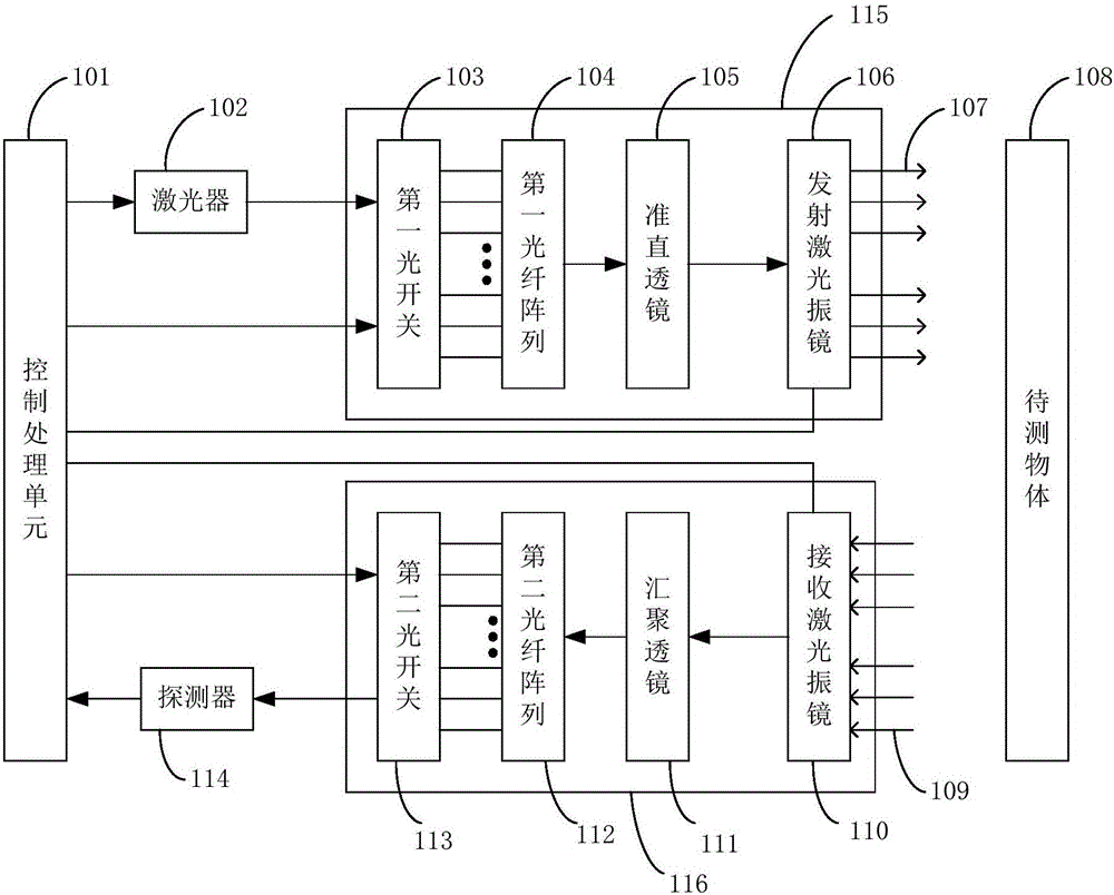
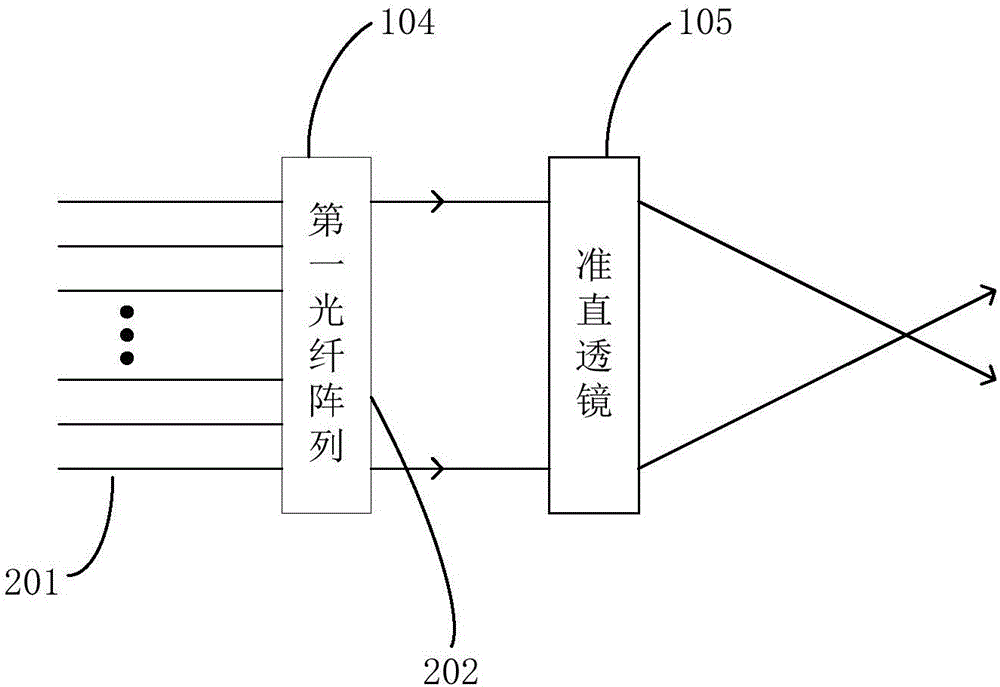
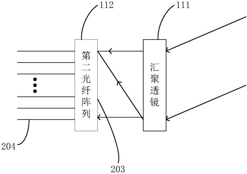
[0042] figure 1 Shown is a schem...


PUM


Abstract

The invention discloses a solid-state laser radar system, which comprises a laser, a detector, an emitting optical system, a receiving optical system and a control processing unit. The emitting optical system comprises a first optical switch, a first fiber array, a collimating lens and an emission laser galvanometer. The receiving optical system comprises a second optical switch, a second fiber array, a convergence lens and a receiving laser galvanometer. By utilizing functions of optical path selection and time division multiplexing of the optical switches, multi-line measurement can be realized through one laser and one detector; through cooperation of the first fiber array and the collimating lens as well as cooperation of the second fiber array and the convergence lens, scanning of a first dimension of a space is realized; and through deflection functions of the emission laser galvanometer and the receiving laser galvanometer on the laser, scanning of a second dimension vertical to the first dimension of the space is realized. The system is low in cost and small in size; and the laser radar system can be driven to rotate without a mechanical scanning mechanism.

Description

Technical field [0001] The invention belongs to the field of laser radar, and specifically relates to a solid-state laser radar system. Background technique [0002] Lidar technology is widely used in navigation, map surveying and mapping, satellite positioning and other fields. In the field of unmanned vehicles, lidar plays a key role in map mapping and scene positioning. [0003] Lidar can be divided into ordinary lidar and solid-state lidar. Ordinary lidar generally requires a mechanical rotation mechanism, which drives the lidar system to perform spatial rotation scanning through rotation; solid-state lidar does not require a mechanical rotation mechanism, and uses optical methods to directly change the emission direction of the output laser to achieve the purpose of scanning space. [0004] The mechanical rotating mechanism of the existing ordinary lidar is generally large in size, inconvenient to install, and has poor long-term stability. At the same time, because scanning i...

Claims


Application Information

Patent Timeline
Patent Type & Authority Applications(China)
IPC IPC(8): G01S7/481G01S17/88
CPCG01S7/4817G01S7/4818G01S17/88
Inventor 齐龙舟
Owner 上海博未传感技术有限公司
Why Eureka
Try Eureka