An Antenna System Applied to Radar 3D Scanning

An antenna system and 3D technology, applied in the field of automatic marking, can solve the problems of difficulty in realizing microwave wavelength operation, complex system and high cost

Active Publication Date: 2019-05-03
SHENZHEN CHENG TECH CO LTD
View PDF4 Cites 0 Cited by
  • Summary
  • Abstract
  • Description
  • Claims
  • Application Information

AI Technical Summary

Problems solved by technology

[0003] Aiming at the deficiencies of the prior art, the present invention provides an antenna system applied to radar 3D scanning, which solves the problem that the existing antenna beam two-dimensional scanning technology system is complicated, the cost is high, and the microwave band wavelength work is difficult to realize

Method used


Image

  • An Antenna System Applied to Radar 3D Scanning
  • An Antenna System Applied to Radar 3D Scanning
  • An Antenna System Applied to Radar 3D Scanning

Examples


Embodiment 1

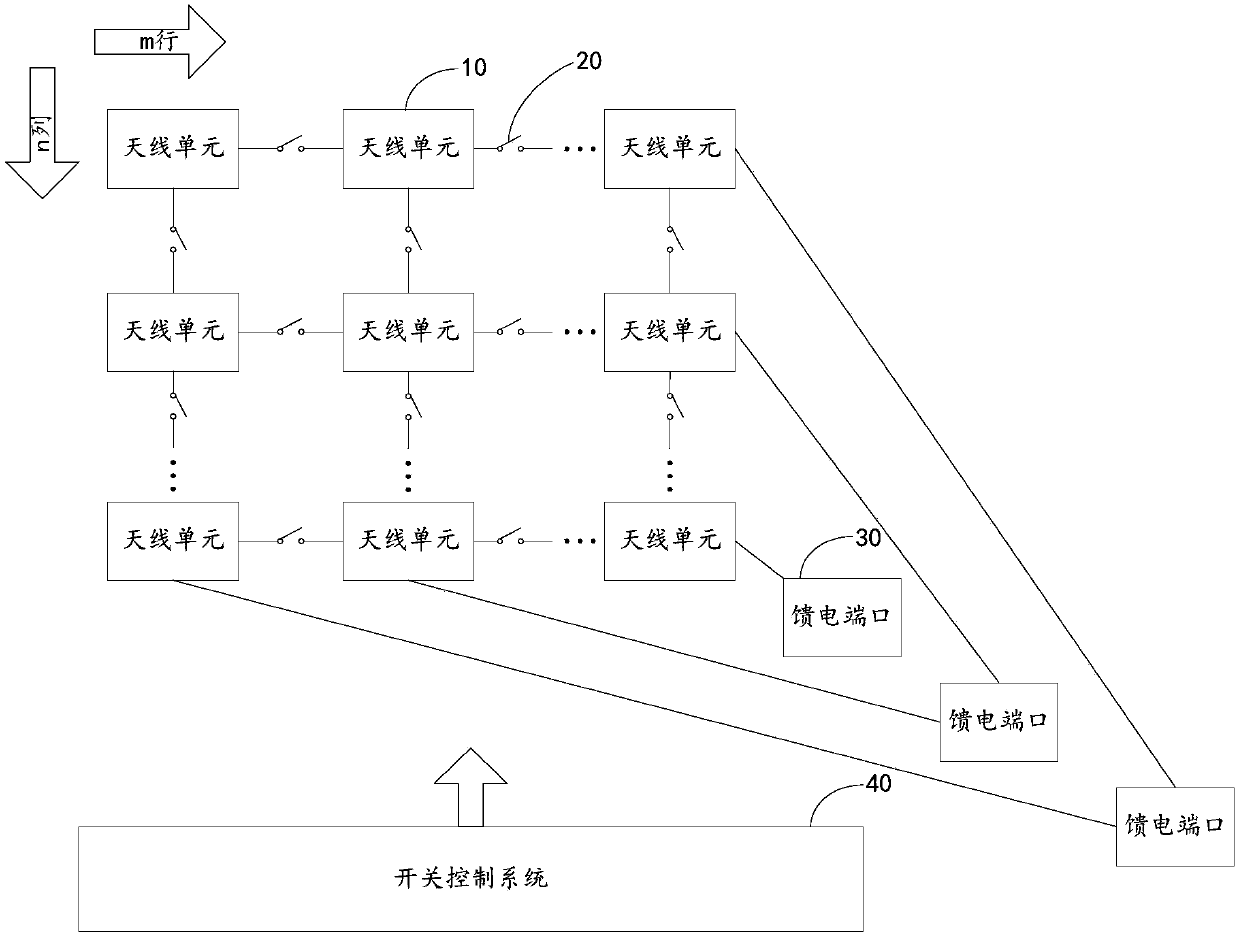
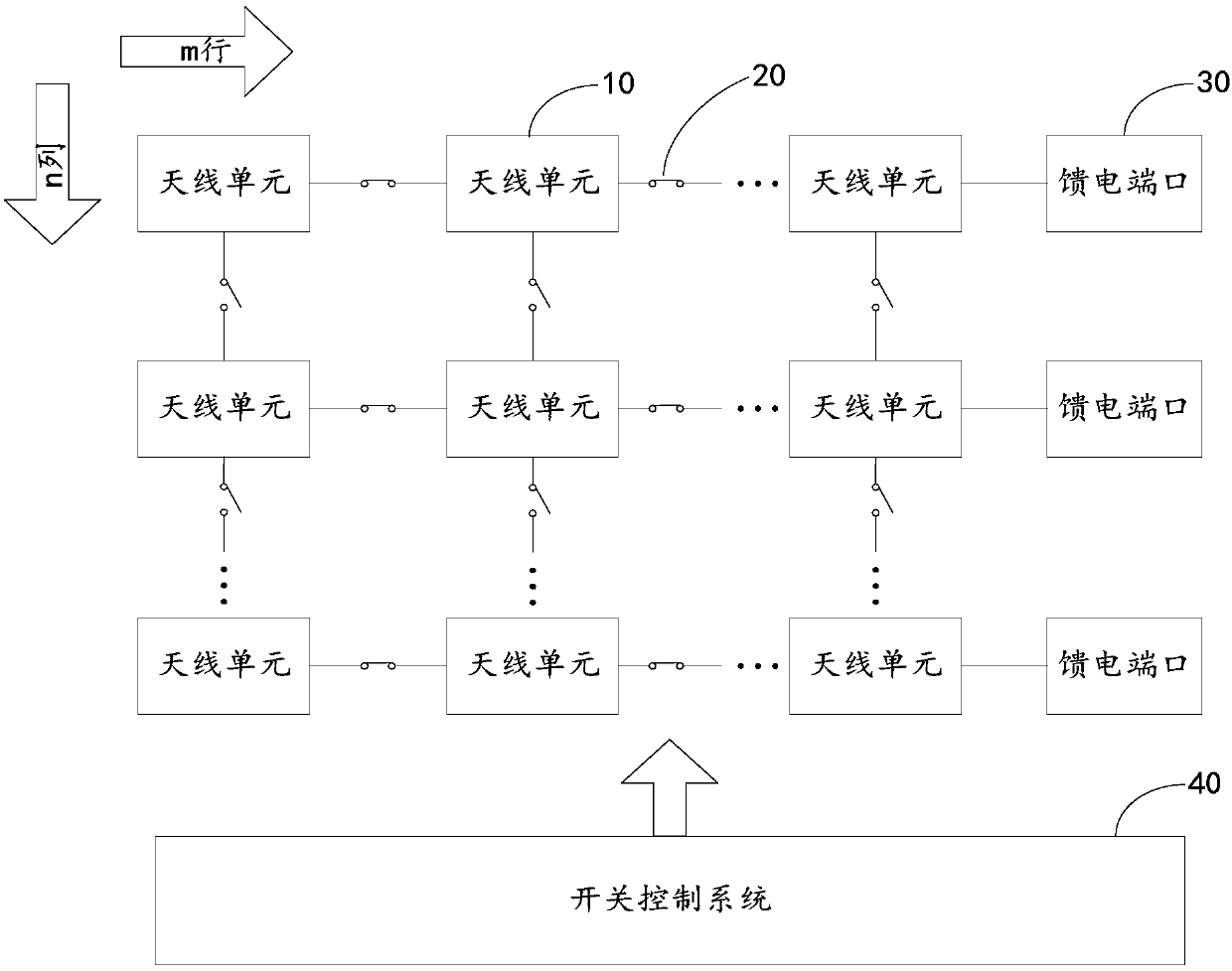
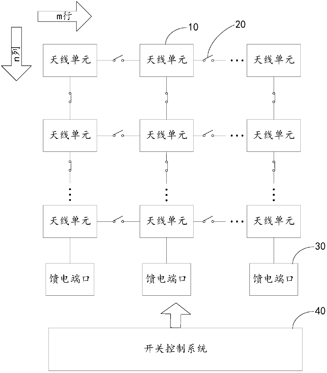
[0027] Such as figure 1 As shown, it is a schematic structural diagram of an antenna system applied to radar 3D scanning according to Embodiment 1 of the present invention. The antenna system includes an antenna unit 10, a control switch 20, a feed port 30 and a switch control system 40;

[0028] The antenna units 10 form an antenna array of m rows×n columns; the antenna array of m rows×n columns is a rectangular antenna array of m rows×n columns arranged at equal intervals between each antenna unit. The antenna unit 10 is a microstrip antenna, a slot antenna, a horn antenna, a waveguide antenna, a dipole antenna and other media capable of propagating and receiving electromagnetic waves with an antenna function.

[0029] The control switch 20 is arranged between each antenna unit 10, and is used to connect the antenna units 10 to form an antenna array of m rows×n columns; the control switch 20 is preferably a radio frequency switch, and the radio frequency switch is composed ...


PUM


Abstract

The invention relates to the technical field of automation identification, and provides an antenna system applied to three-dimensional scanning of a radar. The antenna system comprises antenna units, control switches, feed ports and a switch control system. The antenna units form an m*n antenna array. The control switches are arranged between the antenna units and used for being connected with the antenna units to form the m*n antenna array. The feed ports are connected with the antenna units at the tail ends of m rows and the tail ends of n lines. The switch control system controls the control switches to achieve two-dimensional scanning in the row direction and the line direction of an antenna beam. According to the antenna system, as the radio frequency switches are arranged between the antenna units, the switch control system controls the states of the radio frequency switches to achieve two-dimensional scanning in the row direction and the line direction of the antenna beam, and the three-dimensional scanning requirement of the radar is met.

Description

【Technical field】 [0001] The invention relates to the technical field of automatic identification, in particular to an antenna system applied to radar 3D scanning. 【Background technique】 [0002] The digital beamforming or phased array beam scanning performed by the existing radio frequency microwave band radar array antenna is usually a single-directional beam scanning in the vertical direction or the horizontal direction. If two-dimensional beam scanning in the vertical direction and horizontal direction is to be realized simultaneously to realize radar 3D scanning, the traditional method is a fully distributed phased array or digital array, which must be implemented by multiple independent T / R components or receiving components implemented in a phased array manner. The distributed phased array antenna requires each unit to be fed independently. When the antenna array is large in scale, the number of feed ports is extremely large, which increases the complexity of the sys...

Claims


Application Information

Patent Timeline
Patent Type & Authority Patents(China)
IPC IPC(8): H01Q21/00H01Q3/24
CPCH01Q3/24H01Q21/00
Inventor 陈承文安清儒谭树杰
Owner SHENZHEN CHENG TECH CO LTD
Why Eureka
Try Eureka