Laser three-dimensional imaging scanning method based on dielectric elastic driving

A technology of laser three-dimensional imaging and scanning method, applied in the field of laser radar scanning and laser three-dimensional imaging scanning, can solve the problems of light weight, small size, compact structure, etc., and achieve the effect of light weight, large scanning angle and simple structure

Active Publication Date: 2021-08-20
BEIJING INSTITUTE OF TECHNOLOGYGY
View PDF6 Cites 1 Cited by
  • Summary
  • Abstract
  • Description
  • Claims
  • Application Information

AI Technical Summary

Problems solved by technology

[0003]The purpose of the present invention is to solve the problems of compact structure, small size and light weight in the prior art, and proposes a laser driven by dielectric elasticity 3D imaging scanning system

Method used


Image

  • Laser three-dimensional imaging scanning method based on dielectric elastic driving
  • Laser three-dimensional imaging scanning method based on dielectric elastic driving
  • Laser three-dimensional imaging scanning method based on dielectric elastic driving

Examples


Embodiment Construction

[0019] Specific embodiments of the present invention will be described below in conjunction with the accompanying drawings.

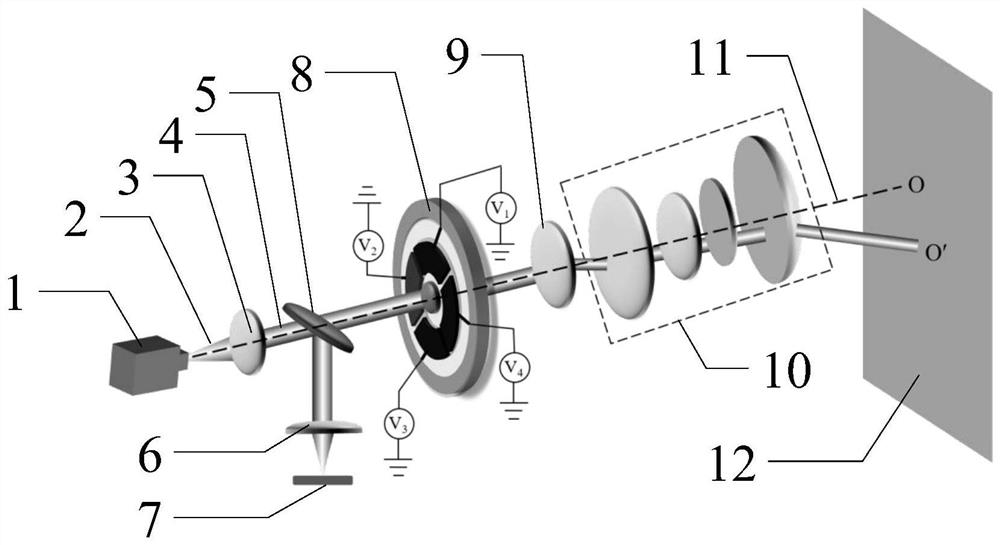
[0020] A laser three-dimensional imaging scanning method based on dielectric elasticity drive disclosed in this embodiment, such as figure 1 As shown, it mainly includes a pulsed laser 1, a pulsed beam 2, a collimating lens 3, a parallel beam 4, a beam splitter 5, a converging lens 6, a photodiode 7, a first lens 8, a second lens 9, a diverging lens group 10, and a light Axis 11, Target 12. The pulsed beam 2 emitted by the pulsed laser 1 becomes a parallel beam 4 after being acted on by the collimating lens 3, and the parallel beam 4 is divided into two beams by the beam splitter 5: (1) one beam propagates downward, and after being acted by the converging lens 6, it is focused On the photodiode 7, the photodiode produces a pulse electric signal, and the peak value of the pulse electric signal is used as the distance timing start moment of the laser thr...


PUM


Abstract

The invention relates to laser radar scanning, in particular to a laser three-dimensional imaging scanning method based on dielectric elastomer driving, and belongs to the field of optical design. A dielectric elastomer is used as a drive, and the two-dimensional scanning of a light beam is realized by using the radial eccentric movement principle of a lens. The movable lens driven by the dielectric elastomer is adhered to the midpoint area of the dielectric elastomer. Four areas are evenly distributed on the peripheral area of the movable lens driven by the dielectric elastomer, the upper surface of the dielectric elastomer in each area is evenly coated with a flexible electrode, and the lower surface of the dielectric elastomer in each area is evenly coated with a ground electrode. The movable lens driven by the dielectric elastomer can generate radial eccentric movement by adjusting voltage combination applied to the four electrodes, and parallel light beams are emitted in a direction having a deflection angle with the optical axis instead of being emitted at an angle parallel to the optical axis after passing through the movable lens driven by the dielectric elastomer and a second lens.Therefore, the scanning of a target is realized.

Description

technical field [0001] The invention relates to laser radar scanning, especially designs a laser three-dimensional imaging scanning method driven by a dielectric elastic body, and belongs to the field of optical design. Background technique [0002] Laser 3D imaging system is widely used in navigation, positioning, surveying and mapping, target recognition and other fields because it can obtain the distance information of the target. According to the presence or absence of scanning components, current laser 3D imaging systems can be divided into scanning and non-scanning. Non-scanning laser 3D imaging usually requires large-area avalanche photodiodes (APDs), and large-area APD detectors are currently difficult to obtain due to complex processing and high cost. The scanning laser 3D imaging system uses the scanning unit to scan the target scene and obtain the 3D information of the target. Traditional scanning elements such as rotating prisms, rotating galvanometers, and mul...

Claims


Application Information

Patent Timeline
Patent Type & Authority Applications(China)
IPC IPC(8): G01S7/481
CPCG01S7/4817G01S7/481
Inventor 程阳郝群曹杰陈传训李志阔
Owner BEIJING INSTITUTE OF TECHNOLOGYGY
Why Eureka
Try Eureka