Unmanned aerial vehicle and method and device for positioning and controlling mobile terminal

A mobile terminal, rotation and translation matrix technology, applied in the positioning and control of mobile terminals, and the field of drones, can solve the problems of high price, inconvenient use, and low investment cost

Inactive Publication Date: 2017-02-22
杭州零智科技有限公司
View PDF13 Cites 12 Cited by
  • Summary
  • Abstract
  • Description
  • Claims
  • Application Information

AI Technical Summary

Problems solved by technology

The positioning accuracy of the motion capture system is high, but the price is extremely expensive, and the entire system needs to be calibrated before use, which is extremely inconvenient to use
[0005] To sum up, it is urgent t

Method used


Image

  • Unmanned aerial vehicle and method and device for positioning and controlling mobile terminal
  • Unmanned aerial vehicle and method and device for positioning and controlling mobile terminal
  • Unmanned aerial vehicle and method and device for positioning and controlling mobile terminal

Examples


Embodiment 1

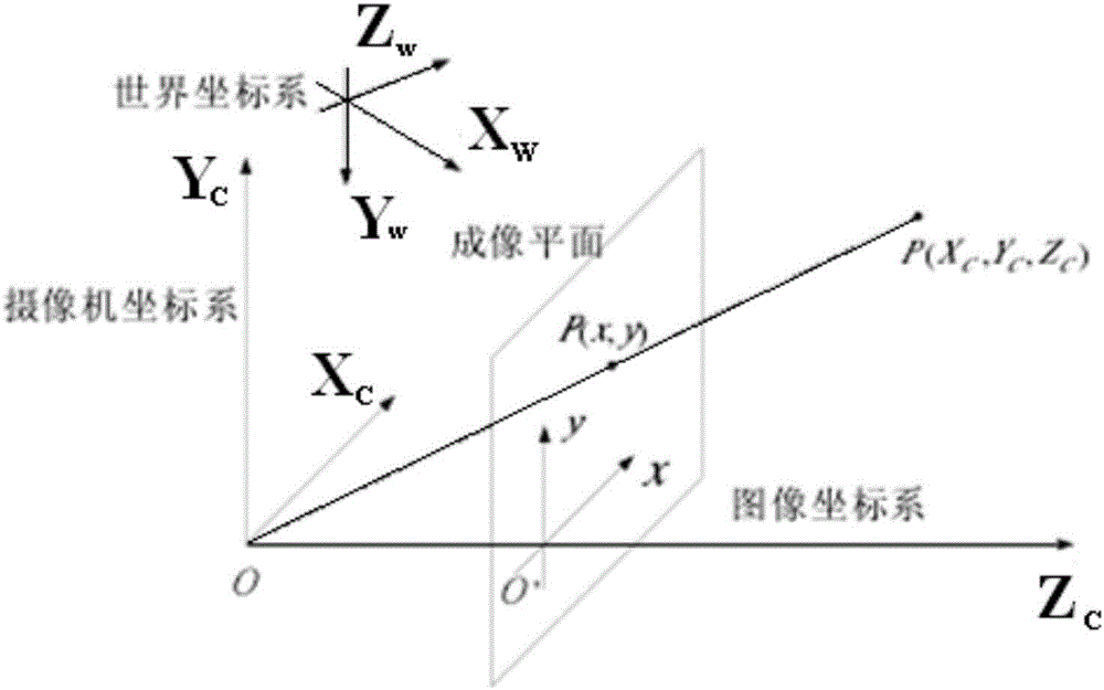
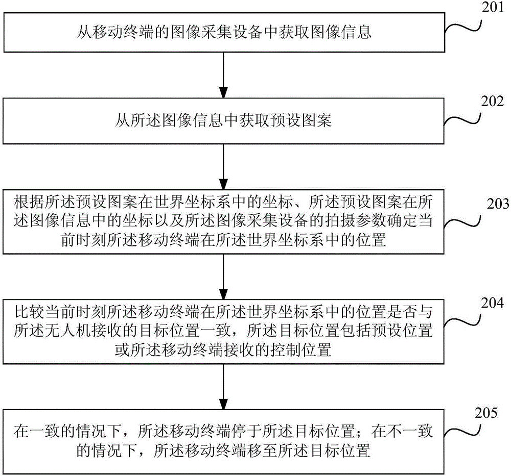
[0200] Embodiment 1: when the UAV executes the hover command, the UAV obtains the position of the UAV in the world coordinate system according to the above formula (1) and the above formula (2) in real time, and compares the position of the UAV in the world coordinate system The real-time position and the preset hovering position can be used to judge whether the UAV is offset or not. Once there is an offset, the speed or speed of the UAV can be controlled according to the current position of the UAV in the world coordinate system. The acceleration is adjusted in the opposite direction of the offset, moving the drone to the preset hover position. In this way, the UAV is always hovering at the preset hovering position.

Embodiment 2

[0201] Embodiment 2: Control the Marker pattern to be in a moving state, the origin of the world coordinate system is on the Marker pattern, the Marker pattern moves, the origin of the world coordinate system moves accordingly, and the world coordinate system moves accordingly. Regardless of whether the Marker pattern moves or not, the vertex coordinates of the Marker pattern in the constructed world coordinate system remain unchanged. If the drone does not make corresponding movement changes, the position of the drone in the world coordinate system also changes, and the position of the Marker pattern in the image information also changes. The UAV obtains the position of the UAV in the world coordinate system according to the above formula (1) and the above formula (2).

[0202] In order to control the running state of the UAV through the Marker pattern, for example: when the UAV needs to fly to the right, control the UAV to fly to the right by moving the Marker pattern to the...

Embodiment 3

[0203] Embodiment 3: Regardless of whether the Marker pattern is in a static state or in a moving state, the position of the Marker pattern in the world coordinate system remains unchanged. Give the UAV a control command and expect the UAV to reach the preset target speed. According to the control command, the drone responds by changing the current speed or acceleration of the drone. In this way, the position of the Marker pattern in the image information also changes. In practical applications, there is a high probability that the UAV will not reach the preset target speed. In this case, the UAV obtains the position of the UAV in the world coordinate system according to the above formula (1) and the above formula (2) in real time, and according to the position of the UAV in the world coordinate system at the current moment and the previous moment The position of the UAV in the world coordinate system and the time difference between the current moment and the previous moment...


PUM


Abstract

The invention relates to an unmanned aerial vehicle and a method and device for positioning and controlling a mobile terminal. The method for positioning the mobile terminal includes the following steps: obtaining the image information from an image acquisition device of the mobile terminal, obtaining a preset mage from the image information, and determining the position of the mobile terminal in a world coordinate system according to a coordinate of the preset mage in the world coordinate system, a coordinate of the preset mage in the image information and a shooting parameter of the image acquisition device.

Description

technical field [0001] The present invention relates to the technical field of positioning and control, in particular to a positioning and control method and device for a mobile terminal and an unmanned aerial vehicle. Background technique [0002] In related technologies, mobile terminal positioning technologies are mainly divided into three types: GPS-based positioning technology, motion capture system-based positioning technology, and color block-based visual positioning technology. in, [0003] GPS-based positioning technology is generally suitable for outdoor environments. However, due to the low accuracy of civilian GPS (only 3 meters), and the existence of problems such as occlusion and multipath effects, it is difficult for GPS-based positioning technology to meet the needs of aircraft in mobile terminals. Accurate positioning and formation flight requirements. In order to improve the positioning accuracy of GPS, a differential GPS positioning system must be used. ...

Claims


Application Information

Patent Timeline
IPC IPC(8): G05D1/12
CPCG05D1/12
Inventor 孙孟孟周炯傅重阳杨建军
Owner 杭州零智科技有限公司
Why Eureka
Try Eureka