
Battery module

A technology for battery modules and single cells, which is applied in the manufacturing of batteries, battery pack components, and secondary batteries, etc., which can solve the high cost of the coating treatment process, the inability to solve the environmental pollution of overflowing glue, and the insulation requirements of the battery surface. Advanced problems, to achieve the effect of improving the utilization rate of glue, meeting the strength, and improving the service life

Pending Publication Date: 2017-02-22
CONTEMPORARY AMPEREX TECH CO
View PDF10 Cites 25 Cited by
  • Summary
  • Abstract
  • Description
  • Claims
  • Application Information

AI Technical Summary

Problems solved by technology

[0003] At present, the design structure of the existing battery pack includes end plates, side plates, batteries, structural glue, and bottom plate. Additional expensive gluing equipment and glue curing equipment are used to realize the process; 2) AB two-component glue is fluid, it is difficult to control the coating area, and it is impossible to solve the environmental pollution caused by overflowing glue and the problem that the amount of glue cannot be guaranteed, and the utilization rate of glue is low. High, and the manufacturing cost remains high; 3) The existing design of the single battery and the single battery is a close-fitting design. During the use of the battery pack, there is no space for the single battery to expand, which affects the service life of the battery; 4 ) In the current design, the close-fitting design of the single battery also has high requirements on the insulation of the battery surface, and the cost of the treatment process such as coating remains high

Method used


Image

  • Battery module
  • Battery module
  • Battery module

Examples


Embodiment Construction

[0036] The battery module according to the present invention will be described in detail below with reference to the accompanying drawings.

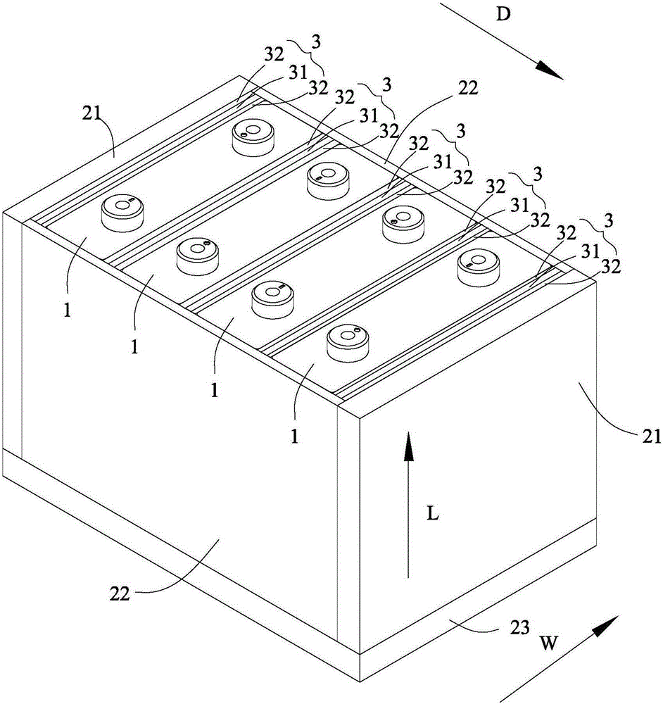
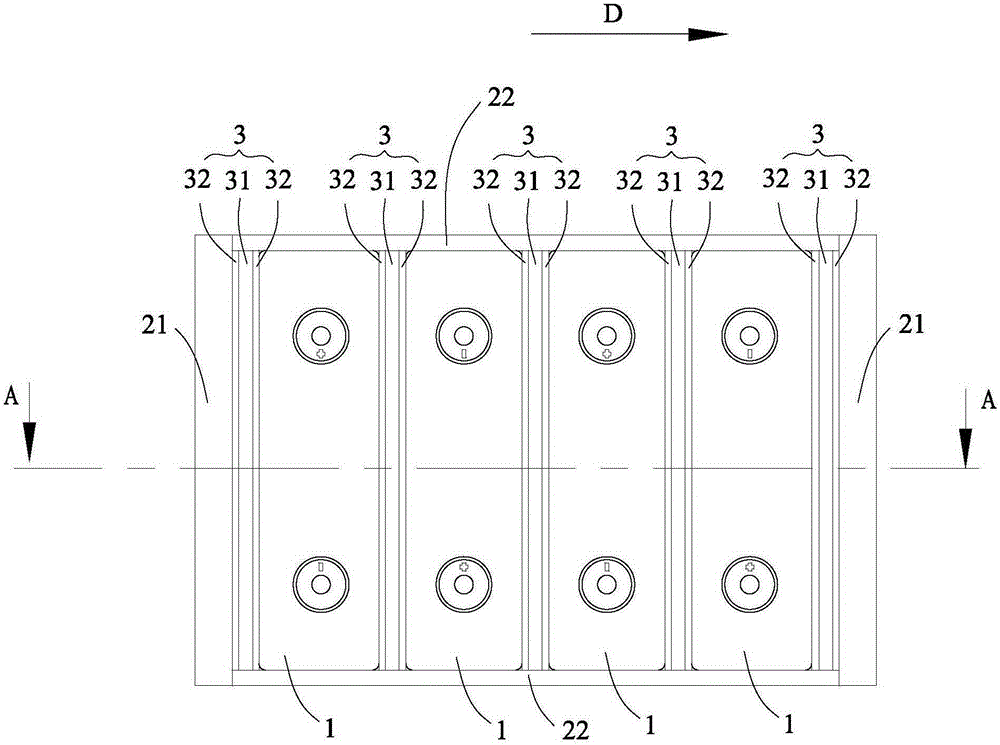
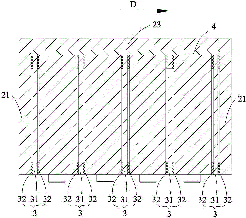
[0037] refer to Figure 1 to Figure 16 , the battery module according to the present invention includes: a plurality of single cells 1 , a fixing mechanism 2 and an insulating film 3 .

[0038] A plurality of single cells 1 are arranged side by side.

[0039] The fixing mechanism 2 is used to fix and accommodate the plurality of single batteries 1 .

[0040] The insulating film 3 is disposed between two adjacent single cells 1 to bond the two adjacent single cells 1 together and to insulate the two adjacent single cells 1 . Each insulating film 3 comprises: insulating substrate 31; The single cells 1 are glued together.

[0041] In the battery module according to the present invention, the insulating film 3 is arranged between two adjacent single cells 1 to bond the two adjacent single cells 1 together and make the gap between the tw...


PUM

PropertyMeasurementUnit
thicknessaaaaaaaaaa

Abstract

The invention provides a battery module. The battery module comprises a plurality of single batteries, a fixing mechanism and insulation films, wherein the plurality of single batteries are arranged in parallel, the fixing mechanism is used for fixing and accommodating the plurality of single batteries, each insulation film is arranged between two adjacent single batteries and is used for making the two adjacent single batteries pasted and isolated, each insulation film comprises an insulation substrate and structural back adhesives, and the structural back adhesives are arranged on a front surface and a rear surface of the insulation substrate and at edges of two opposite sides of each surface of the insulation substrate so that the two adjacent single batteries are pasted. In the battery module according to the invention, spaces for the single batteries to expand and release are separated based on the arrangement of the insulation substrates and the structural back adhesives, the influence of the expansion of the single batteries on the battery module is reduced, the service lifetime of the battery module is prolonged, the shearing strength between adjacent single batteries during the application process of the battery module is improved, and the structural strength of the battery module is improved; and meanwhile, the process is simplified, and the production efficiency is improved.

Description

technical field [0001] The invention relates to the field of batteries, in particular to a battery module. Background technique [0002] Environmental and energy issues are becoming more and more severe, and low-carbon and environmentally friendly energy has become an inevitable choice for future economic development. Hybrid vehicles and electric vehicles, as representatives of new energy vehicles, have been gradually developed and have been recognized by consumers and supported by the government. As the main power source of new energy vehicles, power battery modules have become the main components and key technologies of electric vehicles. Power batteries have become more and more widely used. The most notable feature of the application in the fields of electric vehicles and energy storage power stations is modular assembly, that is, many batteries are assembled into a battery pack, and then multiple battery packs are assembled in series / parallel into a PACK (battery pack...

Claims


Application Information

Patent Timeline
Patent Type & Authority Applications(China)
IPC IPC(8): H01M10/04H01M2/10H01M2/14H01M50/289H01M50/40
CPCH01M10/0413H01M2220/20H01M50/20H01M50/40Y02E60/10Y02P70/50
Inventor 童华桥田峰余峰
Owner CONTEMPORARY AMPEREX TECH CO
Learn More