
Synchronous automatic antenna folding device

An automatic synchronization and antenna technology, applied in the direction of folding antennas, rotating antennas, etc., can solve the problems of time-consuming hard logarithmic period antennas, difficulty in ensuring accuracy, and inability to achieve synchronization, reducing professional skills requirements, lightweight structure, and improving fast response. effect of ability

Pending Publication Date: 2017-02-22
YANSHAN UNIV +1
View PDF6 Cites 12 Cited by
  • Summary
  • Abstract
  • Description
  • Claims
  • Application Information

AI Technical Summary

Problems solved by technology

[0004] In view of the above existing problems, the present invention aims to provide a synchronous and automatic antenna folding device with reasonable structure, which can realize the synchronous folding and unfolding of the hard logarithmic periodic antenna, can improve the efficiency of the hard logarithmic periodic antenna folding and unfolding, and ensure the folding Accurate and unfolding, to improve the time-consuming and labor-intensive manual folding and unfolding of the hard logarithmic periodic antenna, the inability to achieve synchronization, and difficulty in ensuring accuracy, etc.

Method used


Image

  • Synchronous automatic antenna folding device
  • Synchronous automatic antenna folding device
  • Synchronous automatic antenna folding device

Examples


Embodiment Construction

[0021] The present invention will be further described below in conjunction with the accompanying drawings and embodiments.

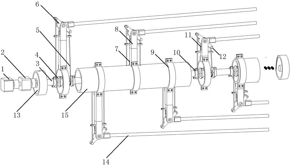
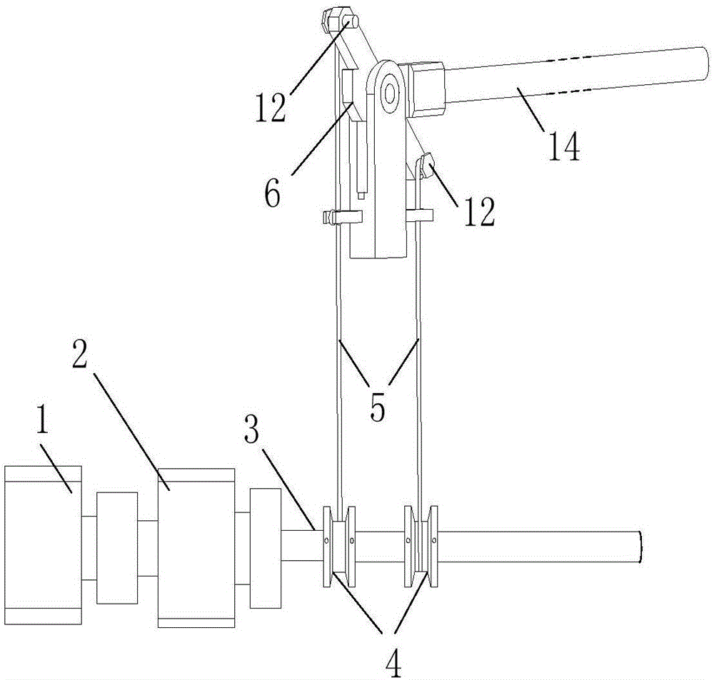
[0022] An antenna synchronous automatic folding device according to the embodiment of the present invention, its overall structure is as follows figure 2 shown. transmission system such as image 3 shown. The transmission process is motor 1-reducer 2-rotating shaft 3-turntable 4-drawing rope 5-rotating frame 6-antenna vibrator 14, that is, motor 1 provides power for the rotation of rotating shaft 3, and rotating shaft 3 drives turntable 4 to rotate, and then drives the pulley The rope 5 moves, and the pull rope 5 drives the rotating frame 6 to rotate, so as to realize the rotation of the antenna vibrator 14 and achieve the purpose of folding or unfolding. Wherein, the motor 1 is connected with the speed reducer 2 through a shaft coupling, the speed reducer 2 is connected with the rotating shaft 3 through a shaft coupling, and the left and right stay...


PUM


Abstract

The invention discloses a synchronous automatic antenna folding device. The device comprises a transmission system and a height regulation block. The transmission system comprises a motor, a reducer and a rotation shaft which are connected sequentially. A rotation disk is placed on the rotation shaft. The rotation shaft is provided with a rotation disk axial positioning mechanism. The rotation disk is provided with a overload protection mechanism. A rotation frame is supported by a height regulation block and a support frame, and can rotate around a pin roll of the support frame. The support frame is provided with a rotation frame limit mechanism. The left and right pull ropes have either side tightened and the other side loosened. One end of either pull rod is connected with the rotation disk, the other end is connected with the rotation frame, wherein the middle section is tightened tensely through a tensioning mechanism of the support frame. The height regulation block is connected with an antenna main pipe. Through the transmission of the rotation shaft, rotation disk and pull rod, the rotation frame drives an antenna rotor to rotate, thus achieving the folding or unfolding of all the antenna vibrators. The device achieves the automation of the antenna folding and unfolding processes. The folding and unfolding of all the antenna vibrators are completely synchronous. The device has the advantages of having a high efficiency and high accuracy, having a reasonable transmission, being simple in structure, and being both reliable and stable.

Description

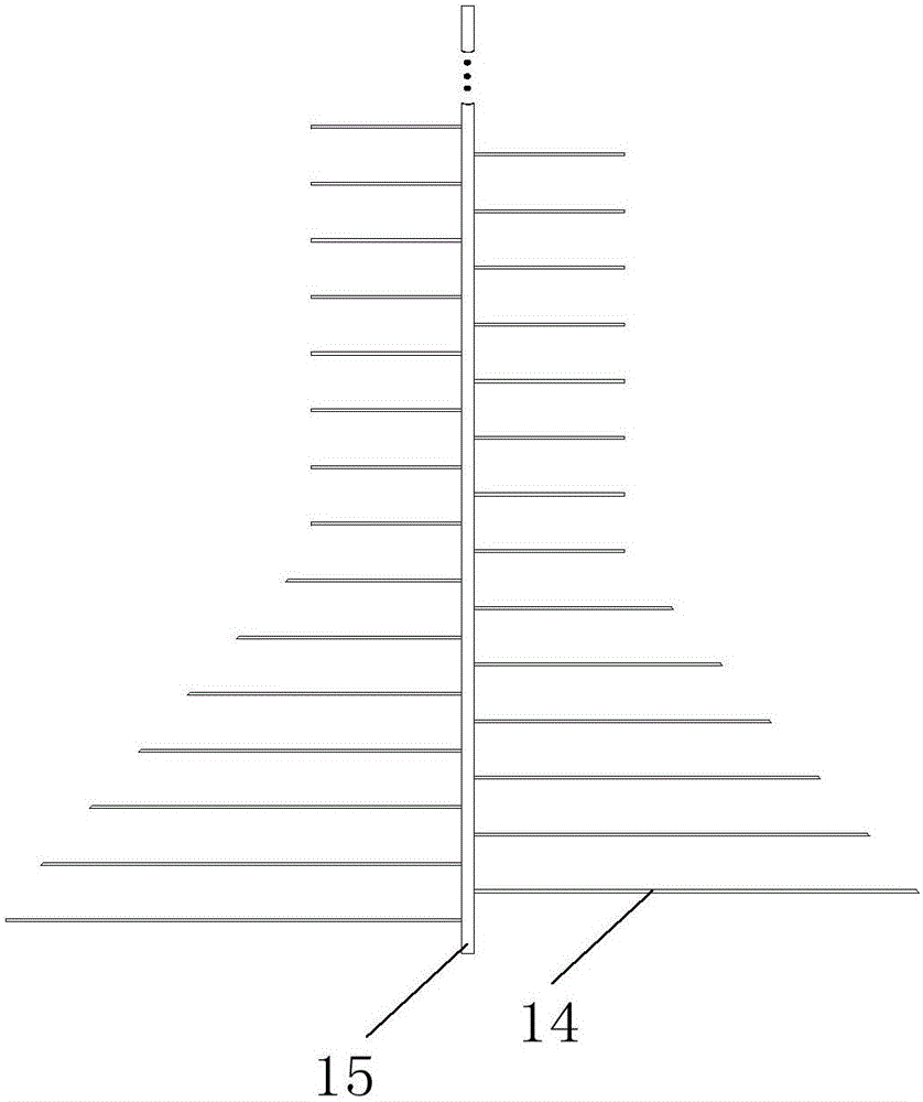
technical field [0001] The invention relates to an antenna device, in particular to a synchronous automatic folding device for a hard logarithmic periodic antenna. Background technique [0002] Antennas are widely used in radio systems such as communications, broadcasting, television, radar and navigation, and are essential devices for effectively radiating and receiving radio waves. like figure 1 As shown, the logarithmic periodic antenna is composed of the main antenna 15 and the antenna vibrator 14. It is a communication antenna that can receive and send short and medium wave signals. It can be used for both point-to-point communication and technological digital signal measurement. [0003] Due to the needs of communication, the number of antenna oscillators is as many as dozens, and the expansion size of the logarithmic periodic antenna can reach several meters. In the working state, all antenna oscillators are completely perpendicular to the main tube to receive signal...

Claims


Application Information

Patent Timeline
IPC IPC(8): H01Q1/08
CPCH01Q1/08H01Q1/084
Inventor 曾达幸樊明洲李建军陆海坤蔺占中段艳宾何其洪周挺侯雨雷
Owner YANSHAN UNIV
Learn More