Optical module automatic temperature compensation device and control method thereof

A technology of a temperature compensation device and a control method, which is applied to lasers, laser parts, electrical components, etc., can solve the problems of time-consuming workload, poor flexibility, and failure of compensation methods.

Active Publication Date: 2018-12-21
THE 44TH INST OF CHINA ELECTRONICS TECH GROUP CORP
View PDF5 Cites 1 Cited by
  • Summary
  • Abstract
  • Description
  • Claims
  • Application Information

AI Technical Summary

Problems solved by technology

Combined with the actual application environment of the optical module, when the temperature changes, the slope efficiency of the laser changes discretely, and the threshold current will also change accordingly, which will cause the traditional compensation method to fail
Therefore, in the full temperature range (-40°C to 85°C) or a more severe temperature range, it is difficult to realize the optical module. The traditional compensation method is relatively limited and has poor flexibility. Usually, it is necessary to replace the soldering resistor and continuously verify it. Or repeatedly adjust the configuration parameters at high and low temperatures, time-consuming and heavy workload

Method used


Image

  • Optical module automatic temperature compensation device and control method thereof
  • Optical module automatic temperature compensation device and control method thereof
  • Optical module automatic temperature compensation device and control method thereof

Examples


Embodiment Construction

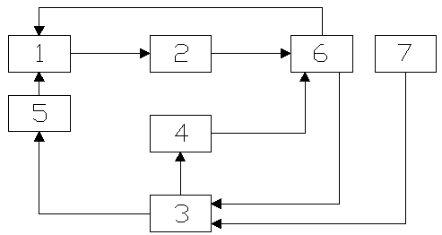
[0032] An optical module automatic temperature compensation device, the innovation of which is: the optical module automatic temperature compensation device consists of a comparator 1, a bias current adjustment module 2, a processing module 3, a modulation current control module 4, and a bias reference correction register 5 and Composed of a temperature sensor; the PD detector of the laser 6 in the optical module is connected to the comparator 1 and the processing module 3 respectively, and the processing module 3 is connected to the temperature sensor, the bias reference correction register 5 and the modulation current control module 4 respectively, and the bias reference correction The register 5 is connected to the comparator 1, the comparator 1 is connected to the bias current adjustment module 2, the modulation current control module 4 is connected to the modulation current input end of the laser 6, and the bias current adjustment module 2 is connected to the bias current i...


PUM


Abstract

The invention provides an automatic temperature compensation device for an optical module. The automatic temperature compensation device for an optical module comprises a comparator, a bias current adjusting module, a processing module, a modulation current control module and a bias reference correction register and a temperature sensor. Based on the automatic temperature compensation device for an optical module, the invention also provides a control method of the automatic temperature compensation device for an optical module. The automatic temperature compensation device for an optical module, and the control method thereof are provided. The automatic temperature compensation device for an optical module enables an output signal of a laser to keep stable optical power and extinction ratio in the wide temperature range all the time.

Description

technical field [0001] The invention relates to a laser control technology, in particular to an optical module automatic temperature compensation device and a control method thereof. Background technique [0002] With the application of access network, FTTH (Fiber to the Home), 3G, 4G and 10Gbit / s Ethernet standards, and Fiber Channel 10Gbit / s, the application of optical modules is becoming more and more extensive. The construction of domestic 4G and FTTx has brought an inflection point growth to the production of optical modules, but the sharp increase in production capacity has also put forward strict requirements for the mass production of optical module manufacturers. In addition, since high-speed optical modules (2.488, 3.125, 6, 10Gbps, etc.) with a wide temperature range (-40°C to 85°C) are popular in the market, the stability of the output optical power and extinction ratio of optical modules in a wide temperature range becomes a key factor. outstanding problems in ...

Claims


Application Information

Patent Timeline
Patent Type & Authority Patents(China)
IPC IPC(8): H01S3/131
CPCH01S3/1317
Inventor 周本军胡伟叶峻宏张敏黄雨新
Owner THE 44TH INST OF CHINA ELECTRONICS TECH GROUP CORP
Why Eureka
Try Eureka