Direct-current distribution box of charging pile

A technology of DC distribution box and charging pile, applied in the direction of battery/battery traction, electric vehicles, electrical components, etc., can solve the problems of damaged charging cables and charging plugs, single function, exhaust gas pollution, etc., to improve work efficiency, Diversified functions and time-saving effects

Active Publication Date: 2017-02-22
天津筋斗祥云网络科技有限公司
View PDF4 Cites 5 Cited by
  • Summary
  • Abstract
  • Description
  • Claims
  • Application Information

AI Technical Summary

Problems solved by technology

[0002] Due to the increasing number of traditional fuel vehicles, the environmental pollution caused by the exhaust gas emitted by vehicles is also becoming more and more serious. As a new topic of green new energy technology, automobiles have gradually entered people's field of vision. Electric vehicles have the advantages of zero emission, low noise, and relatively simple structure. The effect is not good, it is easy to damage the single battery of the car, and it cannot guarantee normal charging. At present, most of the charging devices (charging piles) for pure electric vehicles are vertical exposed types, and most of the distribution boxes are installed on the charging piles. Cables and charging plugs are often hung outside the distribution box. Charging cables and charging plugs are easy to be stolen, and long-term exposure to sunlight or rain can easily cause damage to charging cables and charging plugs. Existing charging piles There is only charging function, and the function is single. Therefore, we propose a charging pile DC distribution box, which can not only charge the vehicle but also clean the vehicle.

Method used


Image

  • Direct-current distribution box of charging pile

Examples


Embodiment Construction

[0016] The following will clearly and completely describe the technical solutions in the embodiments of the present invention with reference to the accompanying drawings in the embodiments of the present invention. Obviously, the described embodiments are only some, not all, embodiments of the present invention.

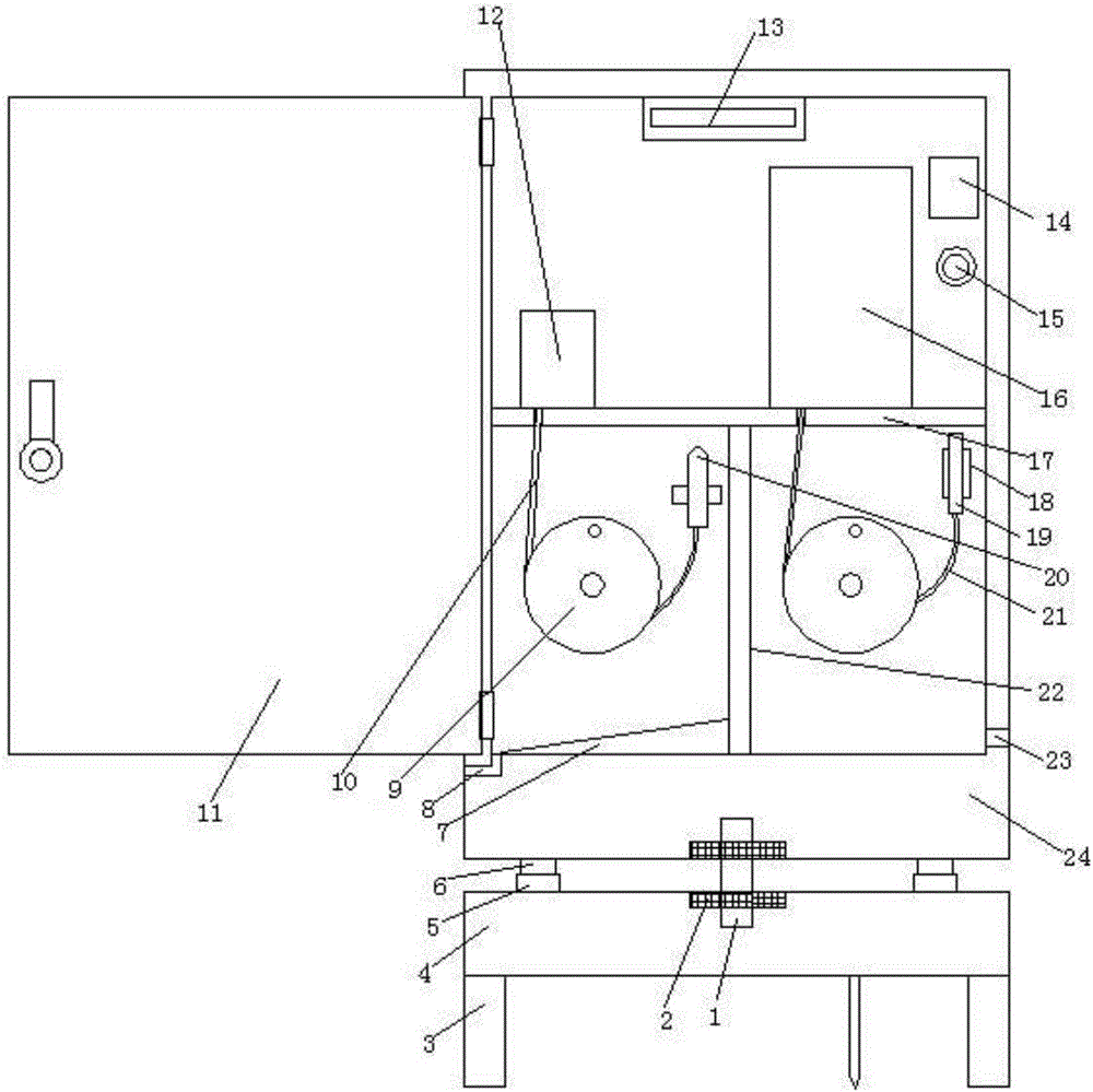
[0017] refer to figure 1 , a DC power distribution box for charging piles, comprising a base, a housing 24 with an opening on one side and a box door 11, the top of the base is equipped with a housing 24, and the opening of the housing 24 is connected with a box door 11 through a hinge, and the box door 11 is equipped with a buckle, the base includes a base plate 4 and a fixed column 3, the bottom of the base plate 4 is provided with fixed columns 3 on both sides, and the top of the base plate 4 is provided with a first rotating shaft 1 and an annular slide rail 5, and the first rotating shaft 1 is located at In the middle position of the annular slide rail 5, the tw...


PUM


Abstract

The invention discloses a direct-current distribution box of a charging pile. The direct-current distribution box comprises a base, a shell with an opening in one side, and a box door. The shell is mounted at the top end of the base, the opening of the shell is connected with the box door through a hinge, and a buckle is mounted on the box door. The base comprises a bottom plate and fixed columns, the fixed columns are arranged on the two sides of the bottom end of the bottom plate, and a first rotary shaft and an annular sliding rail are arranged at the top end of the bottom plate. The first rotary shaft is located in the middle of the annular sliding rail, and the two ends of the first rotary shaft are connected with the bottom plate and the shell respectively. Bearings are arranged at the joints of the first rotary shaft, the bottom plate and the shell, and sliding blocks are arranged on the two sides of the bottom end of the shell. A water pump and a cleaning chamber are arranged in the shell, therefore, a vehicle can be cleaned while being charged, time is saved, work efficiency is improved, and the distribution box of the charging pile has diversified functions. The base is arranged at the bottom of the shell, the sliding blocks and the annular sliding rail are arranged between the base and the shell, and vehicles in different directions can be conveniently charged and cleaned.

Description

technical field [0001] The invention relates to the technical field of charging piles, in particular to a DC power distribution box for charging piles. Background technique [0002] Due to the increasing number of traditional fuel vehicles, the environmental pollution caused by the exhaust gas emitted by vehicles is also becoming more and more serious. As a new topic of green new energy technology, automobiles have gradually entered people's field of vision. Electric vehicles have the advantages of zero emission, low noise, and relatively simple structure. The effect is not good, it is easy to damage the single battery of the car, and it cannot guarantee normal charging. At present, most of the charging devices (charging piles) for pure electric vehicles are vertical exposed types, and most of the distribution boxes are installed on the charging piles. Cables and charging plugs are often hung outside the distribution box. Charging cables and charging plugs are easy to be st...

Claims


Application Information

Patent Timeline
Patent Type & Authority Applications(China)
IPC IPC(8): H02B1/46B60L11/18B60S3/04
CPCB60L50/50B60S3/04H02B1/46Y02T10/70
Inventor 皮普军
Owner 天津筋斗祥云网络科技有限公司
Why Eureka
Try Eureka