Charging pile, charging system and charging control method

A charging pile and circuit technology, applied in charging stations, battery circuit devices, electric vehicle charging technology, etc., can solve the problems of large charging harmonic current and low power factor

Pending Publication Date: 2017-02-22
HUBEI UNIV OF ARTS & SCI
View PDF3 Cites 16 Cited by
  • Summary
  • Abstract
  • Description
  • Claims
  • Application Information

AI Technical Summary

Problems solved by technology

[0004] Aiming at the problems of large charging harmonic current and low power factor in the above-mentioned prior art, the present invention provides a charging pile, a charging system and a charging control method, which can not only improve the power factor of the AC input side, but also reduce the charging time. Harmonic current

Method used


Image

  • Charging pile, charging system and charging control method
  • Charging pile, charging system and charging control method
  • Charging pile, charging system and charging control method

Examples


Embodiment 1

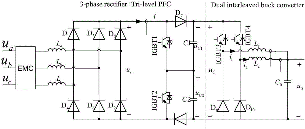
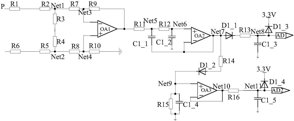
[0052] Embodiment 1 provides a charging pile, including a power conversion circuit and a sampling circuit. The sampling circuit is used to collect the voltage and current of a specific point in the power conversion circuit, and send it to the sampling port of the microprocessor to assist the microprocessor to realize the control of the charging process of the power conversion circuit.

[0053] figure 1 A schematic circuit diagram of a power conversion circuit is shown. Such as figure 1 As shown, the power conversion circuit includes a three-phase three-level power factor corrector (hereinafter referred to as three-phase three-level PFC) and a double interleaved parallel step-down chopper converter (hereinafter referred to as a double interleaved parallel buck converter). What is described in the figure is a double interleaved parallel buck converter, and a triple interleaved parallel buck converter can also be used in actual use. The input end of the three-phase three-level...

Embodiment 2

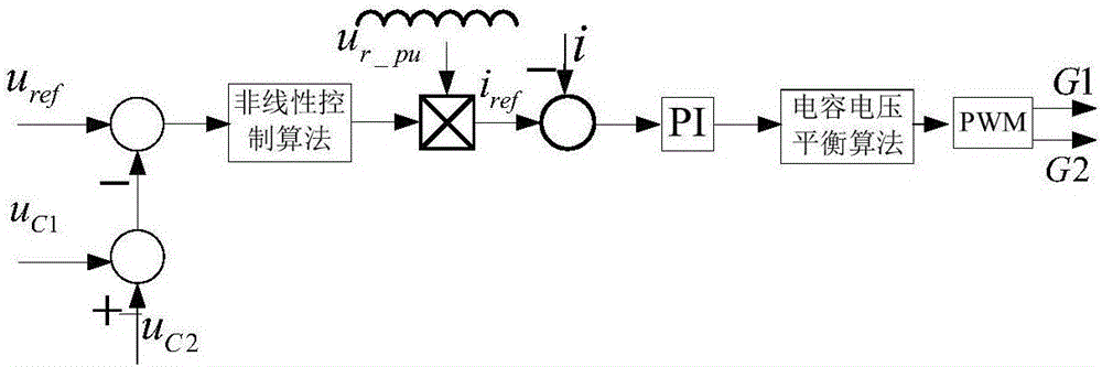
[0074] Embodiment 2 provides a charging control method for a charging pile, the method includes the following steps:

[0075] After the charging process starts, the microprocessor adopts nonlinear The proportional-integral control algorithm controls the output voltage of the three-level boost circuit to obtain the command current of the three-phase three-level power factor corrector;

[0076] The microprocessor calculates the duty ratio by using a linear proportional-integral control algorithm according to the command current of the three-phase three-level power factor corrector and the output current of the three-phase uncontrolled rectifier circuit collected by the sampling port;

[0077] The microprocessor adopts the midpoint balance algorithm to adjust the duty cycle, generates two switching signals, and uses the two switching signals to drive the three-phase three-level power factor corrector, so that the output voltage of the three-level boost circuit is constant ;

[...


PUM


Abstract

The invention provides a charging pile, a charging system and a charging control method, and belongs to the technical field of power electronics. The charging pile comprises a power conversion circuit and a sampling circuit, wherein the power conversion circuit comprises a three-phase three-level power factor corrector and an interleaved buck chopping converter; the input end of the three-phase three-level power factor corrector is connected with a three-phase power grid, and the output end of the three-phase three-level power factor corrector is connected with the input end of the interleaved buck chopping converter; and the output end of the interleaved buck chopping converter is used for connecting a charging gun. The power conversion circuit can be used for improving the power factor on the alternating current input side and reducing the harmonic current and harmonic voltage of charging; and a switching pipe in the power conversion circuit has small voltage stress and small current stress. The charging pile provided by the invention is a power grid-friendly charging pile.

Description

technical field [0001] The present invention relates to the field of power electronics technology and control technology, in particular to a charging pile, a charging system and a charging control method. Background technique [0002] In recent years, electric vehicles have been rapidly popularized as a green means of transportation. For this reason, charging piles have also emerged as the times require. The charging pile accesses AC power from the power grid. After conversion and processing by the internal power circuit, the AC power is converted into controllable DC power to charge electric vehicles. This power conversion function needs to be realized by a power conversion circuit. [0003] A power conversion circuit is an electric energy conversion device that converts one kind of electric power into another kind of electric power. The power conversion circuit of the existing charging pile generally adopts a single-stage power conversion circuit or a two-stage power conv...

Claims


Application Information

Patent Timeline
Patent Type & Authority Applications(China)
IPC IPC(8): H02J7/04B60L11/18
CPCH02J7/045B60L53/00Y02T10/72Y02T10/70Y02T10/7072Y02T90/14
Inventor 闵晶妍陈红兵
Owner HUBEI UNIV OF ARTS & SCI
Why Eureka
Try Eureka