Laminated iron core, method for manufacturing laminated iron core, and punch for caulking formation used in the method

A manufacturing method and stacking direction technology, applied in the manufacture of inductors/transformers/magnets, stator/rotor bodies, magnetic cores/yokes, etc., can solve the problems of difficulty in forming V-stack rivets, deformation, cracks on the bottom surface, etc. Deformation prevention, excellent magnetic properties, strong connection effect

Inactive Publication Date: 2017-02-22
MITSUI HIGH TEC INC
View PDF10 Cites 10 Cited by
  • Summary
  • Abstract
  • Description
  • Claims
  • Application Information

AI Technical Summary

Problems solved by technology

[0005] However, it is difficult to form V-stack riveting in a thin plate with a thickness of 0.2mm or less.
[0006] The main reason for this is that usually in the formation of V-stack riveting, the bottom surface is bulged and the slope is stretched, so cracks occur from the bottom surface.
[0007] In addition, in the case of V-stack riveting, there is also a problem that the periphery of the area where the V-stack riveting is formed is deformed because both inclined surfaces are pressed into the lower core sheet to connect the adjacent core sheets.

Method used


Image

  • Laminated iron core, method for manufacturing laminated iron core, and punch for caulking formation used in the method
  • Laminated iron core, method for manufacturing laminated iron core, and punch for caulking formation used in the method
  • Laminated iron core, method for manufacturing laminated iron core, and punch for caulking formation used in the method

Examples


Embodiment Construction

[0046] Next, embodiments for embodying the present invention will be described with reference to the drawings, so that the present invention can be understood.

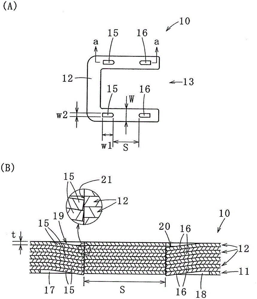
[0047] First, refer to figure 1 , figure 2 , the laminated iron core 10 according to one embodiment of the present invention will be described.

[0048] Such as figure 1 As shown in (A) and (B), the laminated iron core 10 is used for a motor, and is formed by laminating a plurality of core pieces 11 and 12 that are concave (U-shaped) in plan view. In addition, the shape of a core piece is not limited to this, It can change variously according to the kind of motor to manufacture (for example, the kind, size, etc. of a laminated core, hereinafter the same).

[0049] When using this laminated iron core 10, for example, four laminated iron cores 10 are arranged at the center of each side of an imaginary square in a plan view, and each laminated iron core 10 is directed toward the central position of the imaginary squa...


PUM

PropertyMeasurementUnit
thicknessaaaaaaaaaa
widthaaaaaaaaaa
widthaaaaaaaaaa

Abstract

The invention provides a laminated iron core, a method for manufacturing the laminated iron core, and a punch for caulking formation used in the method. Solid stack riveting stack can also be carried out by means of thin plates of thickness of 0.2mm or less. The laminated core (10) is formed with a plurality of iron chips (12) punched out from a sheet (14) having a thickness of 0.2 mm or less; one end portion is continuous, the other parts are separated and tilted; the overlapping pieces (15,16) of the adjacent iron chips(12) are fitted into the opening portions (19, 20) to connect the plurality of iron chips (11,12); the overlapping rivet protrusions (15,16)are arranged at intervals (S), and the other end portions of the pair of overlapping rivet protrusions (15, 16) are formed in the direction or phase away from each other. The manufacturing method includes a stack riveting protrusions forming step, a punching step, and a laminating step, and the overlapping rivet protrusions (15, 16) are formed in the stack riveting process. And a punch portion (15, 16) for forming the above-mentioned stacking protrusions(15,16) is provided symmetrically with respect to the punch (30).

Description

technical field [0001] The present invention relates to a laminated iron core formed by laminating a plurality of core pieces punched out of a thin plate material with a thickness of 0.2 mm or less, a method of manufacturing the same, and a punch for forming a riveting used therefor. Background technique [0002] The laminated iron core constituting the motor is manufactured, for example, by punching out a thin electromagnetic steel sheet into a predetermined shape using a press line, stacking a predetermined number of sheets, and connecting them by riveting. [0003] As this clinching, there are known a clinching in which an electrical steel sheet is half pierced (so-called flat clinching) and a clinching in which an electrical steel sheet is separated to form a slope (so-called V clinching). [0004] In recent years, as the performance of electric motors has improved, there has been an increase in laminated iron cores using thinner electrical steel sheets. The thinner the...

Claims


Application Information

Patent Timeline
Patent Type & Authority Applications(China)
IPC IPC(8): H02K1/06H02K15/02
CPCH02K1/06H02K15/02H01F3/02B21D28/10H01F41/0233H02K2201/09B21D28/24
Inventor 桥本彰博
Owner MITSUI HIGH TEC INC
Why Eureka
Try Eureka