
A thyristor dimming control system for LED brightness adjustment

A brightness adjustment and control system technology, which is applied in the field of LED brightness adjustment, can solve the problems that the theoretical adjustment range cannot be reached, the dimming range is limited, and the conduction angle of the thyristor dimmer is limited.

Active Publication Date: 2017-11-28
SOUTHEAST UNIV
View PDF3 Cites 0 Cited by
  • Summary
  • Abstract
  • Description
  • Claims
  • Application Information

AI Technical Summary

Problems solved by technology

In addition, due to the limited conduction angle of the thyristor dimmer, the theoretical adjustment range of 0° to 180° cannot be achieved, thus limiting its dimming range

Method used


Image

  • A thyristor dimming control system for LED brightness adjustment
  • A thyristor dimming control system for LED brightness adjustment
  • A thyristor dimming control system for LED brightness adjustment

Examples


Embodiment Construction

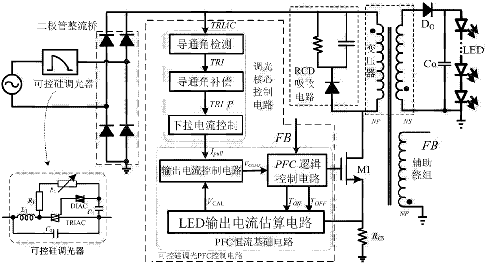
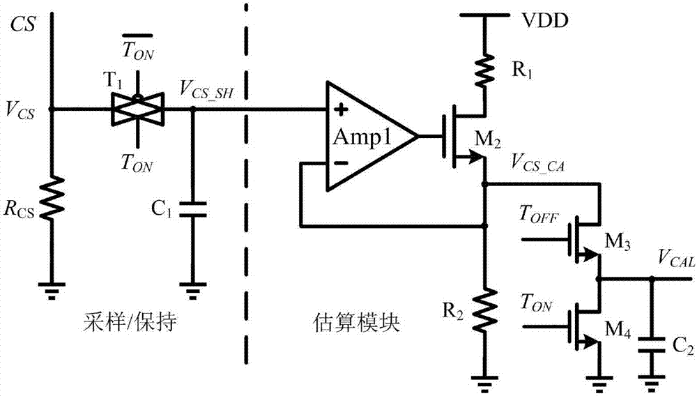
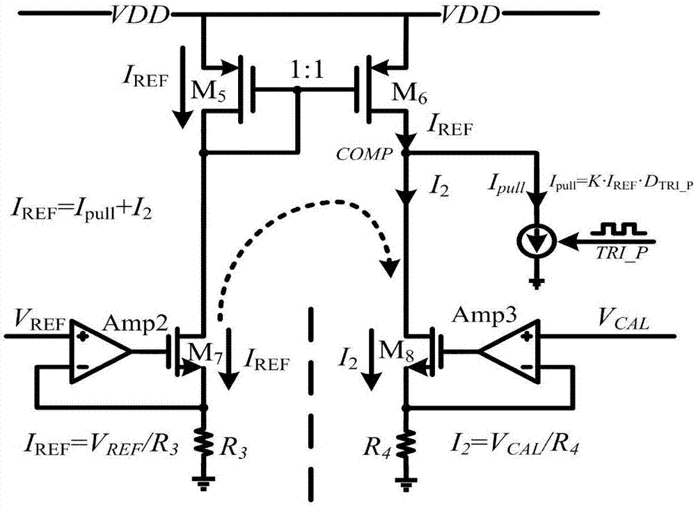
[0044] see figure 1 , the thyristor dimming control system of the present invention comprises a transformer, an NMOS tube M 1 , Primary detection resistor R CS The main topology module of the flyback converter composed of the auxiliary winding and the thyristor dimmer, the diode rectifier bridge, and the RCD absorption circuit are characterized in that: a PFC constant current basic circuit and a dimming control circuit are added, and the PFC constant current basic circuit Including output current estimation circuit, output current control circuit and PFC logic control circuit, dimming control circuit includes conduction angle detection circuit, conduction angle compensation circuit and pull-down current control circuit; SCR dimmer cuts the input bus voltage Wave processing, after the diode rectifier bridge, on the one hand, it is connected to the positive end of the primary winding of the transformer and one end of the resistor and one end of the capacitor in the RCD absorpti...


PUM


Abstract

A thyristor dimming control system for LED brightness adjustment, which improves and optimizes the dimming control circuit. By introducing conduction angle compensation technology, when the thyristor dimmer is adjusted to the maximum conduction angle, The output current reaches the rated output current value. By optimizing the parameters of the dimming pull-down circuit, when the thyristor dimmer is adjusted to the minimum conduction angle, the output current reaches the minimum value of zero. Aiming at the fact that the human eye is not sensitive to changes in the luminance of high-current LEDs, but sensitive to changes in the luminance of low-current LEDs, the dimming curve is optimized, and a two-stage dimming curve, fast dimming and slow dimming, is designed to achieve two Segment dimming, combined with the corresponding PFC control circuit, not only meets the basic requirements of high power factor, low harmonic pollution, and stable constant current output required by the basic LED drive circuit, but also can dim according to the thyristor. The device can adjust the brightness of LED light in a wide range.

Description

technical field [0001] The invention relates to LED brightness adjustment technology, in particular to a thyristor dimming control system for LED brightness adjustment. Background technique [0002] LED (Light Emitting Diode) has many advantages such as long life, low power consumption, high brightness, and small size. Compared with traditional incandescent lamps, LED lamps only need 1 / 10 of the energy consumption to achieve the same luminous brightness, and the service life can be extended hundreds of times. With the increasing maturity of LED technology research, it is an inevitable trend for LED lighting to replace traditional lighting methods such as incandescent lamps and halogen lamps. [0003] With the continuous deepening of the concept of energy saving and environmental protection and the urgent needs of users for different lights in different environments, the dimmable lighting solution is widely used in home, office, street lights because of its energy saving, ad...

Claims


Application Information

Patent Timeline
Patent Type & Authority Patents(China)
IPC IPC(8): H05B33/08H05B44/00
CPCH05B45/37Y02B20/30
Inventor 常昌远唐瑞李振洪潮曹子轩
Owner SOUTHEAST UNIV
Learn More