Vertical material conveying device for pasting and inserting machine

A feeding device and vertical technology, which is applied in the field of vertical feeding devices for placement and insertion machines, can solve the problems of no bending pins and cutting pins, improving market competitiveness, and large temporary space, etc., to achieve operation and use. Convenience, improving market competitiveness, and small temporary space

Inactive Publication Date: 2017-02-22
宗智辉
View PDF6 Cites 5 Cited by
  • Summary
  • Abstract
  • Description
  • Claims
  • Application Information

AI Technical Summary

Problems solved by technology

[0007] When inserting electronic components into the PCB circuit board, the plug-in machine first needs to reshape the pins of the electronic components (make the pins straight), and then the electronic components can be directly plugged into the PCB. For some The electronic components that need to bend and cut the pins before plugging in. Currently, the feeding devices used to transport the electronic components do not have the function of bending and cutting the pins, and other additional devices are required. processing, its structure becomes extremely complex, and the temporary space is large, which causes great troubles to manufacturers and is not conducive to improving market competitiveness

Method used


Image

  • Vertical material conveying device for pasting and inserting machine
  • Vertical material conveying device for pasting and inserting machine
  • Vertical material conveying device for pasting and inserting machine

Examples


Embodiment Construction

[0029] The present invention will be further described below in conjunction with specific embodiments and accompanying drawings.

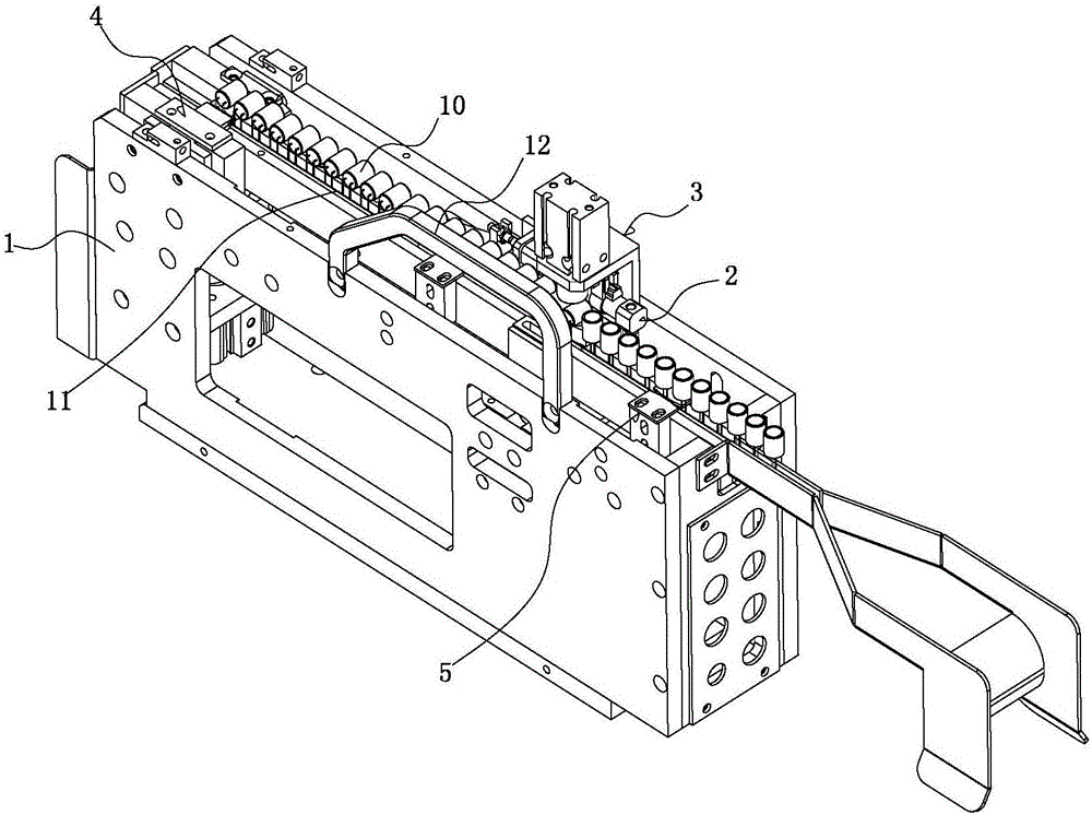
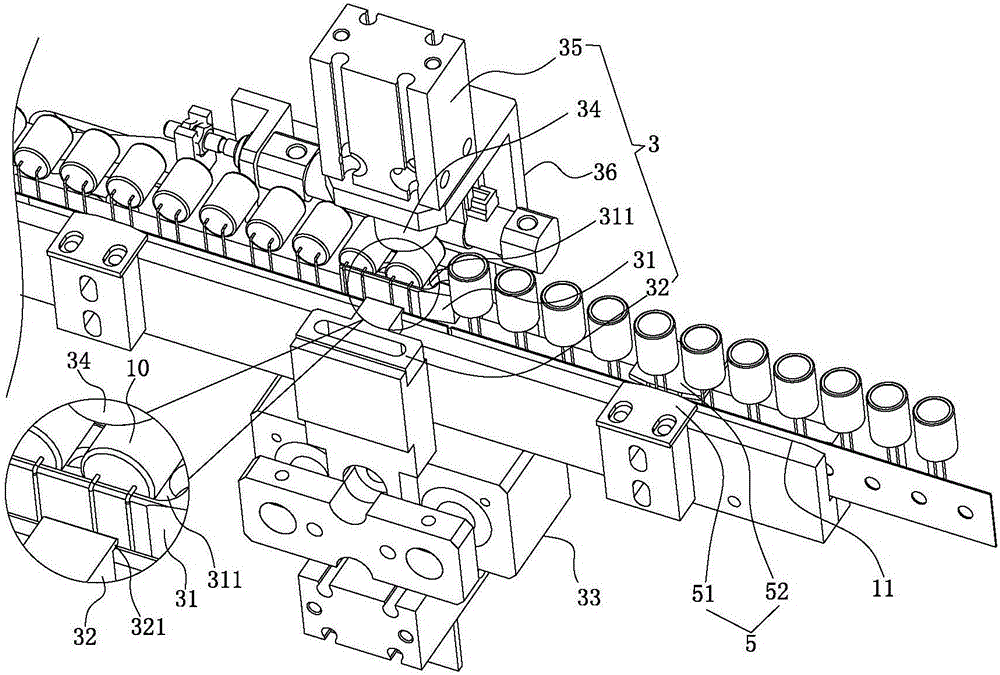
[0030] See Figure 1-5 As shown, it is a vertical feeding device for a sticking and inserting machine, which includes: a machine base 1 , a toggle feeding mechanism 2 installed on the machine base 1 , a bending mechanism 3 and a cutting mechanism 4 .

[0031] The machine base 1 is provided with a longitudinal trough 11 for electronic components 10 to pass through; the machine base 1 is provided with a foldable handle 12, and when in use, directly open the handle to directly lift The invention is very convenient to assemble, operate and use.

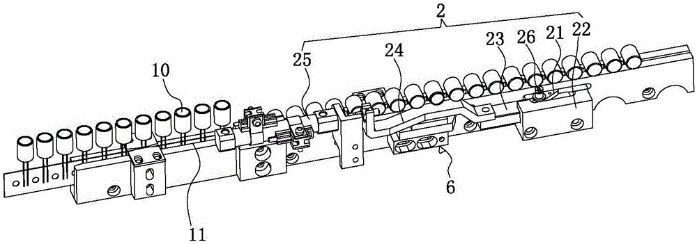
[0032] The toggle block 21 in the toggle feed mechanism 2 stretches into the trough 11; the toggle feed mechanism 2 includes a slide rail seat 22, a slide rail 23 that is worn on the slide rail seat 22, and a slide rail 23 connected drive link 24 and the first cylinder 25 for driving the drive link 24 to mov...


PUM


Abstract

The invention discloses a vertical material conveying device for a pasting and inserting machine. The vertical material conveying device comprises a machine seat, a pulling material conveying mechanism, a bending mechanism and a cutting-off mechanism, wherein a material groove through which an electronic element passes is formed in a longitudinal direction and is arranged on the machine seat; a pulling block in the pulling material conveying mechanism extends into the material groove; the bending mechanism comprises a bending baffle block, a bending push block, a first driving mechanism, a bending press block and a second driving mechanism, the bending stop block is arranged at one side of the machine seat and extends into the material groove; the bending push block is arranged at the other side of the machine seat and is matched with the bending baffle block for bending a lead pin arranged in the electronic element; the first driving mechanism is arranged on the machine seat and is used for driving the bending push block to move to and fro; the second driving mechanism is arranged above the bending baffle plate; the upper end surface of the bending baffle plate is provided with an accommodating groove for accommodating the bended electronic device; the cutting-off mechanism is arranged on the machine seat. During the material feeding of the electronic devices, the lead pins of the electronic devices are directly subjected to bending and cutting-off treatment, so that the electronic devices can be directly inserted and connected onto a PCB (printed circuit board) so as to meet the pasting and inserting requirements; the work efficiency of the pasting and inserting machine is improved.

Description

[0001] Technical field: [0002] The invention relates to the technical field of sticking and inserting machine products, in particular to a vertical feeding device for a sticking and inserting machine. [0003] Background technique: [0004] my country is the world's largest producer and consumer of white goods, and the core component of white goods control is the circuit board. With the continuous development of my country's economy and the gradual improvement of the labor security system, labor costs have gradually increased, and labor-intensive and output fluctuations are the main characteristics of most electronic manufacturers. The automation replacement of a large number of labor-intensive production lines has increasingly become the focus of manufacturers. [0005] The plug-in and debugging of PCB board is the front process of electronic machine production. The traditional PCB board plug-in process relies on manual insertion. The manual plug-in process is particularly...

Claims


Application Information

Patent Timeline
IPC IPC(8): H05K13/02
CPCH05K13/023
Inventor 宗智辉巫杨建
Owner 宗智辉
Why Eureka
Try Eureka