
Rotor for a pyrolysis centrifuge reactor

A technology for reactors and reactor shells, applied in the rotor field of pyrolysis centrifugal reactors, which can solve the problem that large particles may be wedged between the blades 28 and the ablation surface 20a or wedged between the blades 28 and the ablation surface 20a and other problems, to achieve the effect of small residence time

Inactive Publication Date: 2017-02-22
DANMARKS TEKNISKE UNIV
View PDF2 Cites 0 Cited by
  • Summary
  • Abstract
  • Description
  • Claims
  • Application Information

AI Technical Summary

Problems solved by technology

Also, larger particles may become wedged between or between the vane 28 and the ablated surface 20a

Method used


Image

  • Rotor for a pyrolysis centrifuge reactor
  • Rotor for a pyrolysis centrifuge reactor
  • Rotor for a pyrolysis centrifuge reactor

Examples


Embodiment Construction

[0033] In its most general aspect, the present invention relates to a PCR comprising a rotor that can be operated at relatively low rotational speeds while maintaining adequate productivity. By relatively low rotational speed is meant a rotational speed generally below 5000 rpm. Furthermore, the design of the PCR rotor of the present invention is capable of handling solid feeds with different particle sizes.

[0034] Thus, the rotor of the present invention is used to press solid feed, such as biomass, waste or fossil solid fuel, onto the surface of a heat pipe having a temperature between 300°C and 750°C, and also to convey solid feed and solid product through Tubular reactors to convert solid feed into carbon, tar and gas.

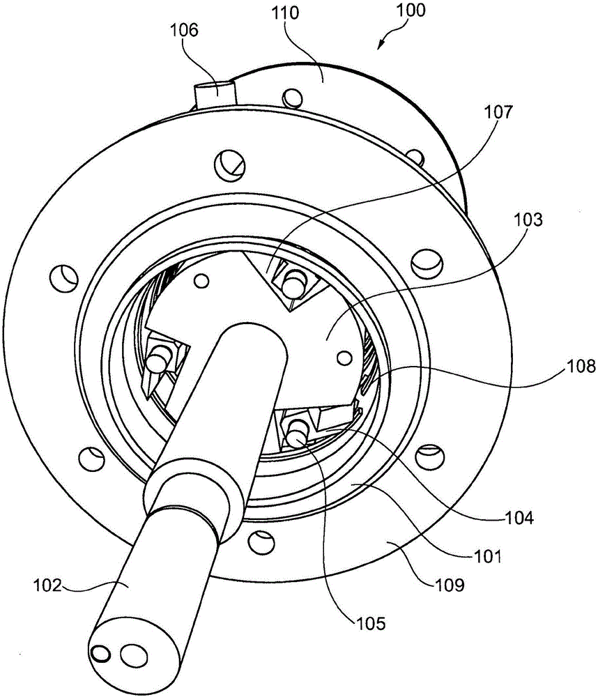
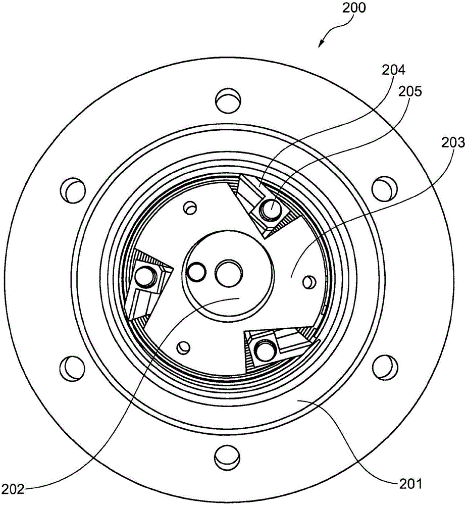
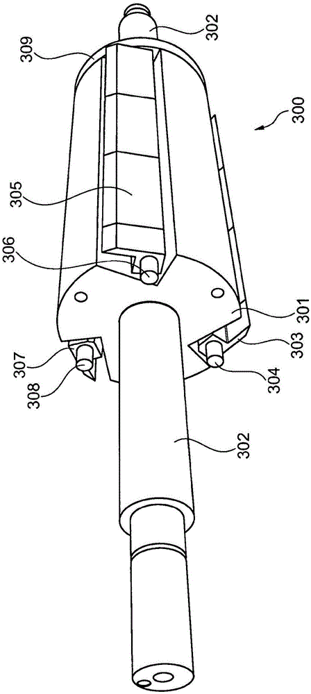
[0035] Refer below figure 1 , shows a PCR 100 having a reactor part 101 enclosing a rotor with a rotor body 103 arranged on a rotor shaft 102 . The solids feed to be processed enters the reactor part through the inlet 106 and leaves the reactor part ...


PUM


Abstract

The present invention relates to a rotor for a pyrolysis centrifuge reactor, said rotor comprising a rotor body having a longitudinal centre axis, and at least one pivotally mounted blade being adapted to pivot around a pivot axis under rotation of the rotor body around the longitudinal centre axis. Moreover, the present invention relates to a pyrolysis centrifuge reactor applying such a rotor.

Description

technical field [0001] The present invention relates to a rotor for a pyrolysis centrifugal reactor (PCR). In particular, the invention relates to a rotor suitable for operation at low rotational speeds. Furthermore, the rotor of the present invention is capable of handling solid feedstocks, such as biomass, having particles of different sizes. Background technique [0002] Various rotor designs for PCR have been proposed over the years. In US7625532 a rotor design is proposed where, in particular Figure 4 and 5 show the details of the proposed rotor. [0003] Refer to US7625532 below Figure 4 , the rotor drum 37 provides a suitable surface on which the blades 28 are attached. The blades 28 are bolted to the rotor drum 37 at 45 degree intervals such that there are eight equally spaced blades 28 positioned around the rotor drum 37 . Each blade 28 is mounted at its first end on a rotor drum 37 by a mechanical support 28a, each blade at Figure 4 The center extends substa...

Claims


Application Information

Patent Timeline
Patent Type & Authority Applications(China)
IPC IPC(8): B01J19/18B01F7/02C10B53/02
CPCB01J19/0066B01J19/18C10B53/02B01F27/092B01F27/112B01F27/2322B01F27/60B01J8/10C10B47/34Y02E50/10B01J6/008
Inventor P·A·延森T·N·郑R·L·克里斯滕森K·达姆-约翰森N·贝克
Owner DANMARKS TEKNISKE UNIV
Learn More