Textile material processing machine

A technology for textile materials and processing machines, applied in textiles and papermaking, combing machines, fiber processing, etc., can solve problems such as expensive, and achieve the effect of optimizing space requirements

Inactive Publication Date: 2012-04-04
MASCHINENFABRIK RIETER AG
View PDF1 Cites 0 Cited by
  • Summary
  • Abstract
  • Description
  • Claims
  • Application Information

AI Technical Summary

Problems solved by technology

This is relatively expensive and requires corresponding controls to drive the individual motors in sync with each other

Method used


Image

  • Textile material processing machine
  • Textile material processing machine
  • Textile material processing machine

Examples


Embodiment Construction

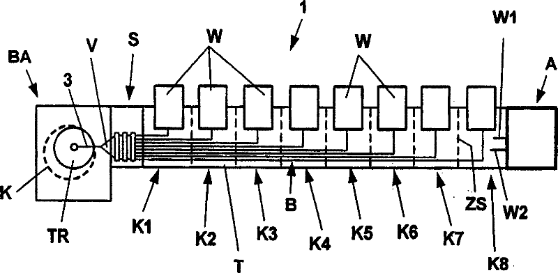
[0048] figure 1 is a plan view of a known combing machine 1 with a total of 8 combing heads K1-K8 arranged next to each other, each combing head having a lap B arranged in front of it for processing. The individual devices of the combing heads K1-K8 (such as nippers, circular combs, detaching rollers, lap rollers, delivery rollers, etc.) are driven by drives A via shafts running longitudinally to each combing head, briefly The two shafts W1 and W2 of each combing head are shown. The driving device actually includes a main motor and a transmission device. In the case of combing heads, it is generally possible to speak of the "gauge" and the gauges together forming the longitudinal section of the comber in which the fiber material is combed.

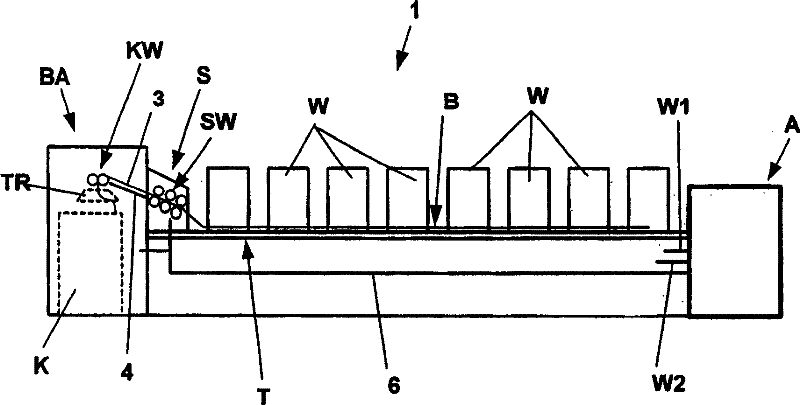
[0049] The individual slivers B made at the individual combing heads K1-K8 are guided over the table T to the drafting device S. as in particular figure 2 As can be seen in , the sliver B is guided upwards obliquely by the table T. G...


PUM


Abstract

The present invention relates to a textile material processing machine which has a plurality of combing devices (X1-X16), at least one cotton sliver (Z) for combing is separately supplied to the combing devices (X1-X16), a cotton sliver (B) is separately formed by mixing the fiber materials combed and transported from the combing heads (X1-X16), then the cotton sliver (B) is transported to the follow drafting device (S) by a guider (FB), the drafting device is provided with adjacent sliver paving devices (BA). In order to provide a comber with simple structure, the comber is arranged with a plurality of combing heads which loading cotton slivers, the combing devices (X1-X16) are suggested to be installed adjacent to each other in a row (G1,G2) on the supporting frame (8), the supporting frame is configured with at least two supporting point on the ground (0), and free room (FR) is formed between the combing devices (X1-X16) and the ground (O). Transport arrangements bring the supply cans in a direction at right angles to the material flow (D) towards the drafting system (S).

Description

technical field [0001] The invention relates to a processing machine for textile materials comprising a plurality of combing units to which at least one sliver is respectively supplied for combing, and the fibrous material which has been combed and outputted at the respective combing units is mixed in order to separately form A sliver is supplied with a guiding device to a subsequent draw frame with an adjacent sliver laying device. Background technique [0002] Combing machines used in practice today generally have 8 combing heads arranged next to each other, each combing head supplying a lap for combing. The fiber webs that have been combed and delivered by the individual combing heads are mixed in order to be made into slivers by known devices and supplied to a subsequent drafting device transversely to the material flow direction of the combing heads on the guiding table. The sliver formed in the draw frame is then laid circularly into the can by the funnel wheel in the...

Claims


Application Information

Patent Timeline
Patent Type & Authority Patents(China)
IPC IPC(8): D01G19/00
CPCD01G19/24D01G19/08
Inventor D・萨默W・斯莱维克
Owner MASCHINENFABRIK RIETER AG
Why Eureka
Try Eureka