Thin film for reflection film or for semi-transparent reflection film, sputtering target and optical recording medium
What is Al technical title?
Al technical title is built by PatSnap Al team. It summarizes the technical point description of the patent document.
a technology of reflection film and film, applied in the field of thin film, can solve the problem of silver undergoing a color change into black, and achieve the effect of increasing the content of chemical compounds
Inactive Publication Date: 2010-02-25
TANAKA PRECIOUS METAL IND
View PDF3 Cites 1 Cited by
Summary
Abstract
Description
Claims
Application Information
AI Technical Summary
This helps you quickly interpret patents by identifying the three key elements:
Problems solved by technology
Method used
Benefits of technology
[0010]Then, the present inventors studied a technique for inhibiting silver atoms from migrating in a thin film; examined silver alloys having the effect; found that it is effective as a further improved remedy for inhibiting the silver atoms from migrating to disperse a silver compound phase in silver or a silver alloy, and thus formed thin film acquires superior reflectance-keeping characteristics; and attained the present invention.
[0012]In the present invention, it becomes possible to inhibit the migration of silver atoms composing a matrix formed of silver or a silver alloy and maintain the flatness of a thin film, by dispersing the phase formed of any of the above-described seven compounds in the matrix, and thereby to inhibit the reflectance from deteriorating even when the thin film has undergone heat.
[0023]A first technique is a method of using a target having a structure and a composition similar to a thin film to be produced, specifically, is a method of using a sputtering target prepared by dispersing a phase of at least one compound selected from the group consisting of a nitride, an oxide, a complex oxide, a nitroxide, a carbide, a sulfide, a chloride, a silicide, a fluoride, a boride, a hydride, a phosphide, a selenide and a telluride of dysprosium, gadolinium, erbium, praseodymium, samarium, lanthanum and yttrium, in a matrix formed of silver or a silver alloy. The method can produce the thin film with the use of one plate of target, accordingly can produce the thin film by a sputtering technique with a form of arranging the target so as to face a substrate, which is ordinarily employed when producing a reflection film, and consequently produce the thin film with adequate productivity. Here, there are further three forms in the sputtering target for producing the thin film according to the present invention, as is described below.
[0032]The reactive sputtering technique may be singly used, but may be used in combination with another technique. For instance, when using the above described special integral target, specifically, using an internally chemically-combined target, a sintered target and an embedded type target, and when it is anticipated that a content of a chemical compound in a thin film will be insufficient only by singly using the targets, it is possible to increase a content of a chemical compound in the thin film by introducing a reactive gas into an atmosphere in a sputtering apparatus. In addition, when producing a thin film by using a co-sputtering technique as well, it is possible to adjust the amount of the chemical compound by using the reactive sputtering technique in combination with the co-sputtering technique.
Problems solved by technology
On the other hand, silver has a problem of undergoing a color change into black through being corroded to decrease its reflectance, because of being inferior in corrosion resistance.
In addition, the reflection film in a display device may cause corrosion due to the atmospheric moisture.
Method used
Image
Click on the blue label to locate the original text in one second.
Reading with bidirectional positioning of images and text.
Examples
Embodiment Construction
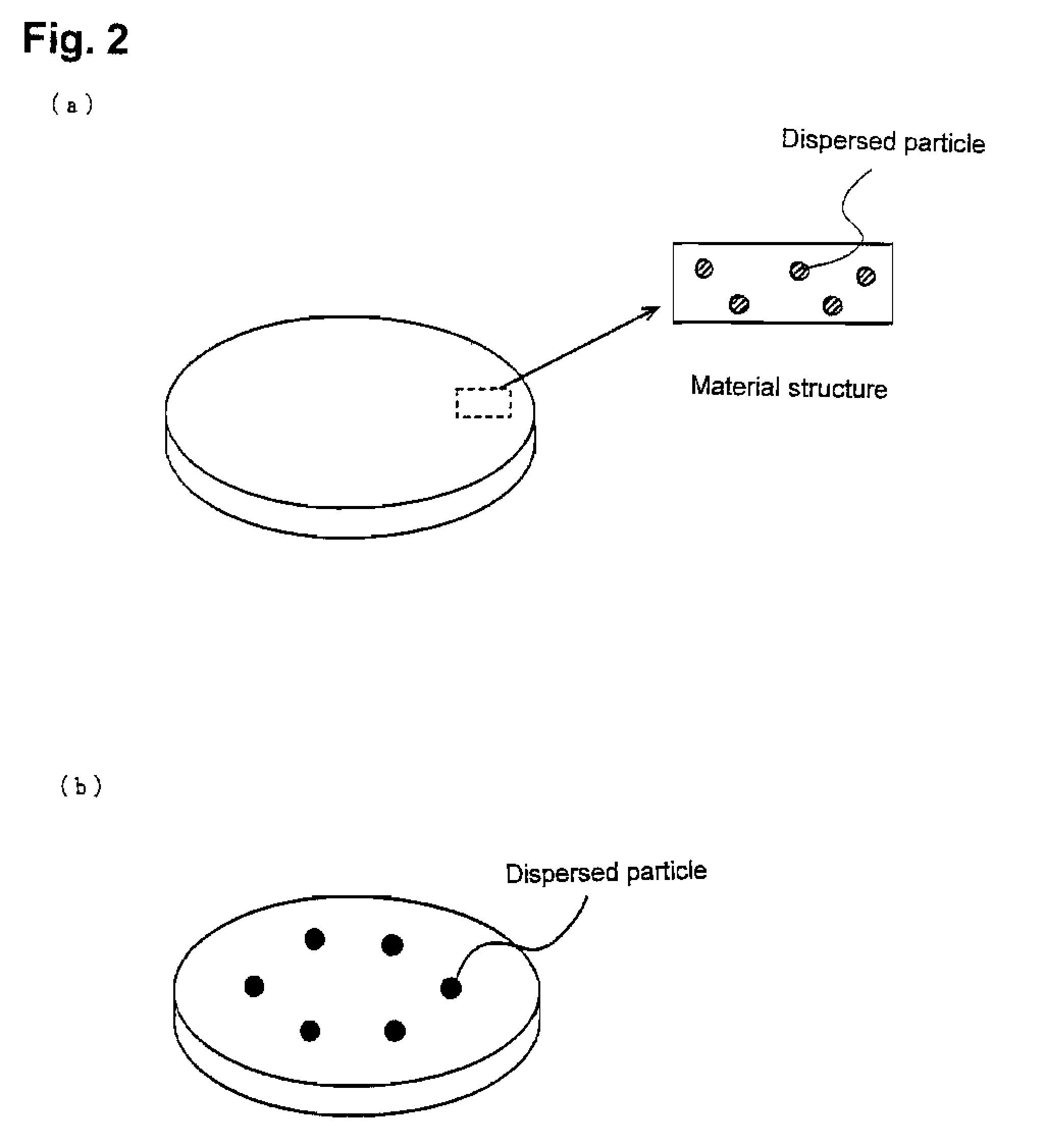
[0035]In the present embodiment, at first, three targets were produced which were an internally chemically-combined type target, a sintered type target and an embedded type target. Then, a thin film was produced not only by using these targets, but also by using a co-sputtering technique and a reactive sputtering technique. By the way, when compositions of a target and a thin film are expressed hereafter, they are expressed in the form of matrix / compound phase, and in the form, a front part of “ / ” represents a matrix and a rear part represents a compound phase. When a silver alloy is used as the matrix, the concentration of an alloying element is expressed by weight % with respect to the silver alloy of the matrix. For instance, Ag-2.0 wt. % Cu-1.5 wt. % Ga / 2.5 wt. % Y2O3 of sample No. 18, means that the thin film (target) has 2.5 wt. % Y2O3 dispersed in the matrix of a silver alloy having a composition of Ag-2.0 wt. % Cu-1.5 wt. % Ga, with respect to a total weight of the thin film...
PUM
Property
Measurement
Unit
particle diameter
aaaaa
aaaaa
temperature
aaaaa
aaaaa
pressure
aaaaa
aaaaa
Abstract
A thin film for a reflection film or a semi-transparent reflection film, having a compound phase formed of at least one chemical compound selected from the group consisting of a nitride, an oxide, a complex oxide, a nitroxide, a carbide, a sulfide, a chloride, a silicide, a fluoride, a boride, a hydride, a phosphide, a selenide and a telluride of dysprosium, gadolinium, erbium, praseodymium, samarium, lanthanum and yttrium, dispersed in a matrix formed of silver or a silver alloy. The thin film may disperse at least one compound selected from the group consisting of a nitride, an oxide, a complex oxide, a nitroxide, a carbide, a sulfide, a chloride, a silicide, a fluoride, a boride, a hydride, a phosphide, a selenide and a telluride of silver, and / or gallium, palladium or copper, in addition to dysprosium or the like, therein. The thin film keeps its reflectance without significant loss even after a long period of use, and prolongs the life of various devices which comprise the thin film as a reflection film, such as an optical recording medium and a display. The thin film is also applicable to a semi-reflective / semi-transparent film used in the optical recording medium.
Description
TECHNICAL FIELD[0001]The present invention relates to a thin film useful as a reflection film or a semi-transparent reflection film used in an optical recording medium, a display and the like. The present invention particularly relates to the thin film which shows reflectance that does not decrease even after it is used for a long period of time, and the optical recording medium having the thin film as the reflection film or the semitransparent reflection film.BACKGROUND ART[0002]An optical recording medium, such as a CD-R / RW, a DVD-R / RW / RAM and a Blue-Ray disk, and a display device, such as a liquid crystal display and an organic luminescent display have at least one layer of a reflection film formed therein. For instance, FIG. 1 shows a structure of an HD-DVD (one-sided, dual-layer rewritable disk) which has been developed in recent years, as an example of the optical recording medium. As shown in the example, the optical recording medium has a multilayer structure comprising the ...
Claims
Application Information
Patent Timeline
Application Date:The date an application was filed.
Publication Date:The date a patent or application was officially published.
First Publication Date:The earliest publication date of a patent with the same application number.
Issue Date:Publication date of the patent grant document.
PCT Entry Date:The Entry date of PCT National Phase.
Estimated Expiry Date:The statutory expiry date of a patent right according to the Patent Law, and it is the longest term of protection that the patent right can achieve without the termination of the patent right due to other reasons(Term extension factor has been taken into account ).
Invalid Date:Actual expiry date is based on effective date or publication date of legal transaction data of invalid patent.
Patent Type & Authority Applications(United States)