
Antenna test device, system, method and related equipment

A technology for testing devices and antennas, applied in transmission systems, antenna radiation patterns, transmission monitoring, etc., can solve problems such as false detection, reduced generation efficiency, and difficulty in accurately testing the accurate power of each antenna.

Active Publication Date: 2019-08-27
HUAWEI TECH CO LTD
View PDF4 Cites 0 Cited by
  • Summary
  • Abstract
  • Description
  • Claims
  • Application Information

AI Technical Summary

Problems solved by technology

[0003] When testing the antennas of wireless terminals, each antenna is tested in the whole machine state. Since multiple antennas on the wireless terminal are distributed in different positions, it is difficult to accurately test the accuracy of each antenna during the whole machine test. Power, so there will be a problem of false detection, and the wireless terminal with normal performance will be falsely detected as a bad product, thereby reducing the generation efficiency

Method used


Image

  • Antenna test device, system, method and related equipment
  • Antenna test device, system, method and related equipment
  • Antenna test device, system, method and related equipment

Examples


Embodiment Construction

[0071] This embodiment describes in detail the specific structure of an antenna testing device capable of increasing the power of antennas located at different positions on the terminal to be tested for testing;

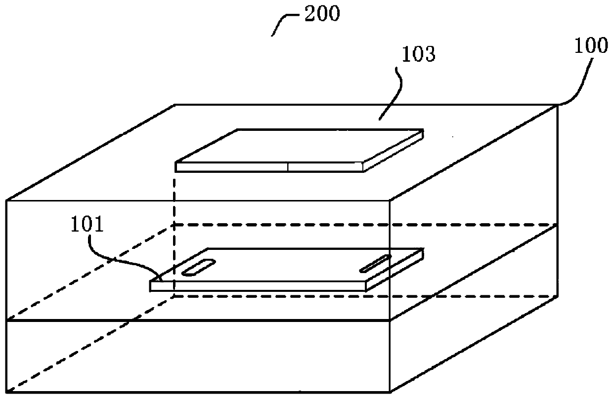
[0072] The specific structure of the antenna testing device provided in this embodiment can be found in figure 1 As shown, among them, figure 1 It is a schematic diagram of the overall perspective structure of a preferred embodiment of the antenna testing device provided by the present invention;

[0073] Depend on figure 1 It can be seen that the antenna testing device 200 specifically includes:

[0074] a shielding box 100, for accommodating the terminal 101 to be tested;

[0075] In this embodiment, the specific shape of the shielding box 100 is not limited, as long as the shielding box 100 can have a shielding effect.

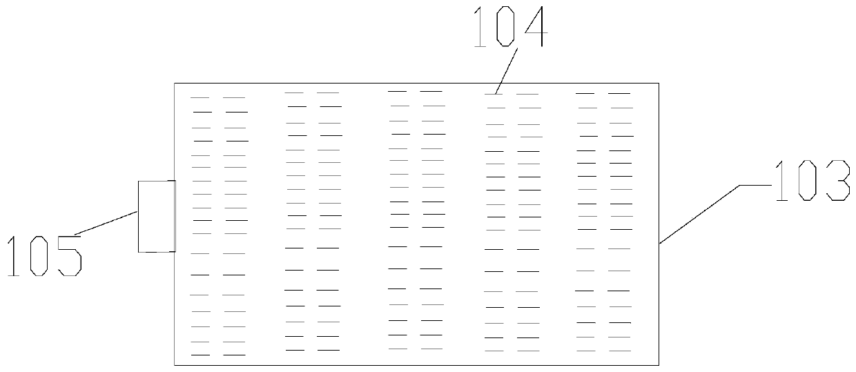
[0076] An antenna array 103 arranged in the shielding box 100;

[0077] This embodiment does not limit how the antenna array 103 is fixedly ...


PUM


Abstract

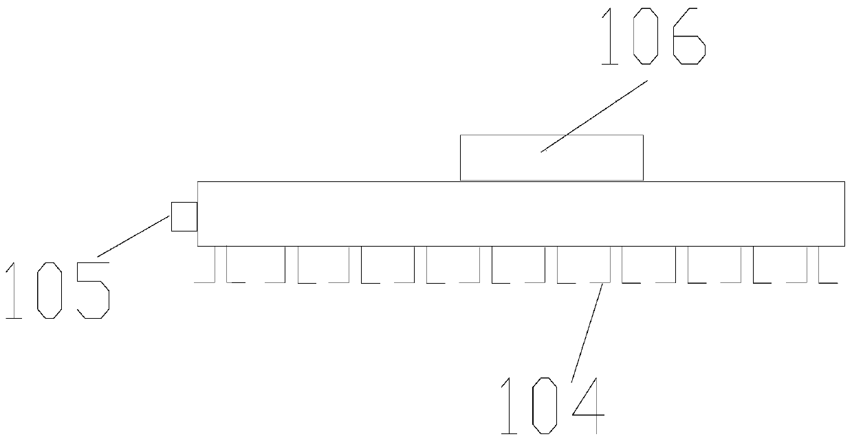
The present invention provides an antenna testing apparatus (200), system and method, and a related device. The antenna testing apparatus (200) comprises a shielding box (100), and a terminal to be tested (101) and an antenna array (103) disposed in the shielding box (100). The antenna array (103) comprises a plurality of test antennae (104) satisfying pre-set conditions, the pre-set conditions referring to non-interference between any two adjacent test antennae (104). A multi-path switch (106) is connected to each test antenna (104). The multi-path switch (106) can conduct a path between a tester (300) and a target test antenna of which target power is greater than or equal to a pre-set value under the control of an information processing apparatus (400), such that the tester (300) only tests a target antenna on the terminal to be tested (101) by means of the target test antenna of which the target power is greater than or equal to the pre-set value. An insertion loss in a test process is low, thereby automatically selecting a target test antenna without manual operations, and improving antenna power test accuracy as well as test efficiency.

Description

technical field [0001] The present invention relates to the field of information processing devices, in particular to an antenna testing device, system, method and related equipment. Background technique [0002] With the enrichment of wireless applications, more and more antennas are integrated into a wireless terminal. For example, wireless terminals such as mobile phones, tablet computers, and multi-function players may be integrated with global positioning system GPS, wireless fidelity Wi-Fi, global mobile communication system GSM, code division multiple access CDMA, universal mobile communication system UMTS, Various communication systems such as near field communication (NFC) and their corresponding multiple antennas. [0003] When testing the antennas of wireless terminals, each antenna is tested in the whole machine state. Since multiple antennas on the wireless terminal are distributed in different positions, it is difficult to accurately test the accuracy of each ...

Claims


Application Information

Patent Timeline
IPC IPC(8): H04B17/00G01R29/10
Inventor 郭钜添
Owner HUAWEI TECH CO LTD
Learn More