CO2 flooding foam oil stream component determining method, and CO2 flooding simulation method

A component model and seepage simulation technology, which is applied in the direction of production fluid, earthwork drilling, wellbore/well components, etc., can solve difficult simulation problems

Active Publication Date: 2017-03-01
CHINA PETROLEUM & CHEM CORP +1
View PDF1 Cites 7 Cited by
  • Summary
  • Abstract
  • Description
  • Claims
  • Application Information

AI Technical Summary

Problems solved by technology

[0004] At present, a large number of CO injection projects have been carried out at home and abroad. 2 Enhanced reservoir recovery studies, which primarily involve CO 2 The analysis of miscible and immiscible displacement phases and seepage mechanism also involves the study of asphaltene precipitation in asphaltene-containing crude oil, but the current model research is difficult to simulate CO 2 Bubble formation during displacement and flow characteristics of "foamy oil stream"

Method used


Image

  • CO2 flooding foam oil stream component determining method, and CO2 flooding simulation method
  • CO2 flooding foam oil stream component determining method, and CO2 flooding simulation method
  • CO2 flooding foam oil stream component determining method, and CO2 flooding simulation method

Examples


Embodiment Construction

[0061] The implementation of the present invention will be described in detail below in conjunction with the accompanying drawings and examples, so as to fully understand and implement the process of how to apply technical means to solve technical problems and achieve technical effects in the present invention. It should be noted that, as long as there is no conflict, each embodiment and each feature in each embodiment of the present invention can be combined with each other, and the formed technical solutions are all within the protection scope of the present invention.

[0062] Also, in the following description, for purposes of explanation, numerous specific details are set forth in order to provide a thorough understanding of embodiments of the invention. It will be apparent, however, to one skilled in the art that the present invention may be practiced without the specific details or in the particular manner described.

[0063] In addition, the steps shown in the flow dia...


PUM


Abstract

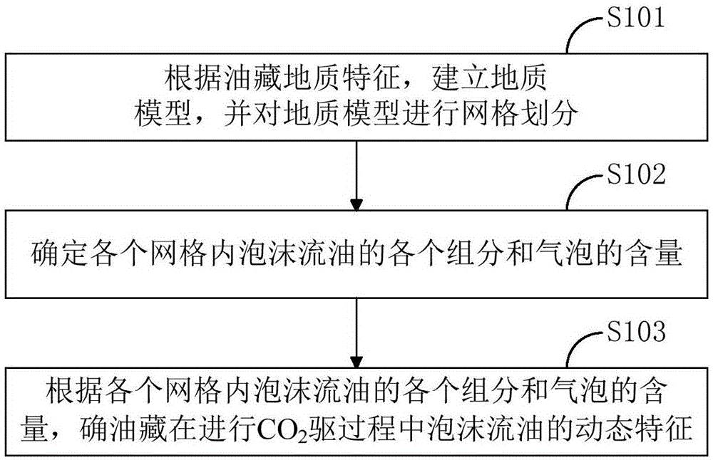
A CO2 flooding foam oil stream component determining method, and a CO2 flooding simulation method are provided; the CO2 flooding foam oil stream component content determining method comprises the following steps: a parameter determining step, determining the thermodynamics parameter, relative permeability and each component of the foam oil stream, and a bubble mol percentage; a component determining step, determining each component and bubble contents according to the parameters obtained in the previous step and a preset component model. The CO2 flooding foam oil stream component determining method uses the preset component model of foam oil stream in a CO2 injection process to accurately simulate the foam oil stream distribution and dynamic characteristic simulation in the gas injection process.

Description

technical field [0001] The invention relates to the technical field of oil and gas exploration and development, in particular to a method for determining CO 2 Method for flooding foamy oil components and CO 2 driving simulation method. Background technique [0002] Most oilfields in my country belong to continental deposits with serious heterogeneity and high viscosity of crude oil. For this type of oilfield, the water flooding recovery can only reach about 33%, so the recovery has a great potential to increase. Among the existing enhanced oil recovery technologies, gas injection flooding is another important way to enhance oil recovery after water flooding, polymer flooding and steam flooding. CO 2 Flooding is listed as the first choice for enhanced oil recovery due to its low cost, remarkable effect, recyclable reuse, non-toxic environmental protection, and good miscibility with crude oil. [0003] CO 2 Flooding "foamy oil flow" is CO 2 A special phenomenon of displ...

Claims


Application Information

Patent Timeline
Patent Type & Authority Applications(China)
IPC IPC(8): E21B43/16
Inventor 贾英史云清严谨石志良郑荣臣
Owner CHINA PETROLEUM & CHEM CORP
Why Eureka
Try Eureka