Eureka AIR delivers breakthrough ideas for toughest innovation challenges, trusted by R&D personnel around the world.

Polarity relay

A relay and polarity technology, applied in relays, electromagnetic relays, electromagnetic relay detailed information, etc., can solve the problems of discontinuous product action process and rising cost, and achieve the effect of avoiding pivot point conversion, stable action, and ensuring continuity.

Active Publication Date: 2017-03-01
TYCO ELECTRONICS SHENZHEN
View PDF5 Cites 1 Cited by
  • Summary
  • Abstract
  • Description
  • Claims
  • Application Information

AI Technical Summary

Problems solved by technology

There are two defects in this magnetic circuit structure: (1) When used in monostable products, it is necessary to add a magnetic spacer between the contact surface of the armature and the iron core or coat an isolation layer on the contact surface of the armature and the iron core , to prevent the resultant electromagnetic force from rising sharply, to ensure that the product can be released normally, which will lead to an increase in cost
[0005] (2) There is a fulcrum conversion during the movement of the armature, resulting in a discontinuous movement of the product

Method used


Image

  • Polarity relay
  • Polarity relay
  • Polarity relay

Examples


Embodiment Construction

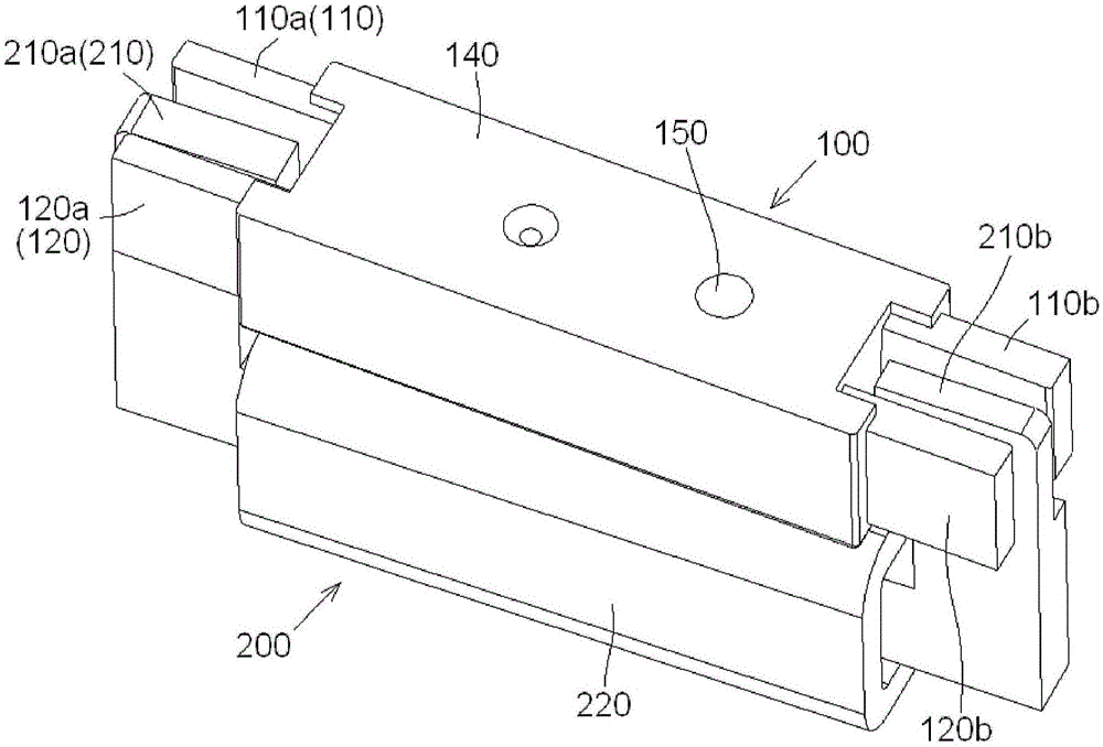
[0029] The technical solutions of the present invention will be further specifically described below through the embodiments and in conjunction with the accompanying drawings. In the specification, the same or similar reference numerals designate the same or similar components. The following description of the embodiments of the present invention with reference to the accompanying drawings is intended to explain the general inventive concept of the present invention, but should not be construed as a limitation of the present invention.

[0030] In addition, in the following detailed description, for purposes of explanation, numerous specific details are set forth in order to provide a comprehensive understanding of the embodiments of the present disclosure. It may be evident, however, that one or more embodiments may be practiced without these specific details. In other instances, well-known structures and devices are shown in diagrammatic form to simplify the drawings.

[0...


PUM


Abstract

The invention discloses a polarity relay. The polarity relay comprises an insulation housing, an armature assembly and a coil assembly. The armature assembly is pivotably installed in the insulation housing so that the armature assembly can be allowed to rotate between a first position and a second position. When the armature assembly is in the first position or the second position, one end of an iron core is in contact with one armature in a pair of armatures, a gap is arranged between the other end of the iron core and the armatures and the other end of the iron core is not in contact with the armatures. According to the invention, the other end of the iron core is separated from the armatures through an air gap, and magnet separation sheets need not to be added between the armatures and the iron core or insulation layers need not to be coated on the armatures and the iron core, so the manufacturing cost is reduced. In addition, the armature assembly rotates around vertical pivoting shaft, so fulcrum transition of the armature assembly during the moving process is avoided; movement is more stable; and continuity of the product in the moving process is ensured.

Description

technical field [0001] The invention relates to a polarized relay, in particular to a monostable polarity relay. Background technique [0002] A polarity relay generally includes an insulating case and a coil assembly, an armature assembly and multiple sets of contact assemblies accommodated in the insulating case. [0003] A coil assembly includes a coil and an iron core. In the prior art, the coil is generally installed in the insulating base of the insulating housing from top to bottom, and the iron core is inserted into the coil. [0004] At present, polarity relays on the market generally use "I"-shaped magnetic circuit structures. One end of the iron core is a fulcrum, and the other end of the iron core rotates around the fulcrum. There are two defects in this magnetic circuit structure: (1) When used in monostable products, it is necessary to add a magnetic spacer between the contact surface of the armature and the iron core or coat an isolation layer on the contac...

Claims


Application Information

Patent Timeline
Patent Type & Authority Applications(China)
IPC IPC(8): H01H50/04H01H50/18H01H50/16
CPCH01H50/04H01H50/16H01H50/18H01H50/163H01H51/2227
Inventor 方光称张晓宁
Owner TYCO ELECTRONICS SHENZHEN
Why Eureka
Eureka Blog
Learn More