Method and apparatus for wireless transmission during high speed movement
A technology of moving direction and moving speed, which is applied in wireless communication, electrical components, etc., and can solve problems such as high complexity LTE
- Summary
- Abstract
- Description
- Claims
- Application Information
AI Technical Summary
Problems solved by technology
Method used
Image
Examples
Embodiment 1
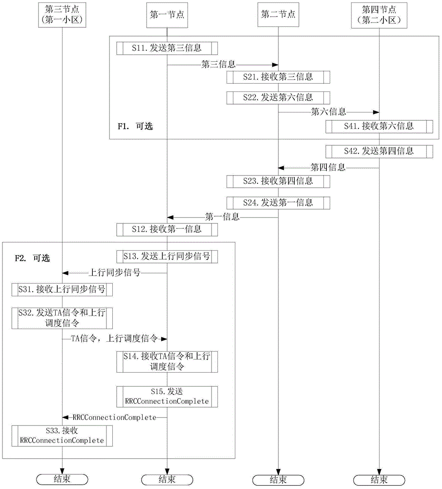
[0103] Embodiment 1 illustrates the switching flow chart of the first node, as shown in the attached figure 1 shown. attached figure 1 , the steps in block F1 and block F2 are optional steps respectively, wherein block F2 describes the process of establishing an RRC connection with the target cell in LTE handover.
[0104] for first node , receiving the first information in step S12.
[0105] for second node, receiving the fourth information in step S23, and sending the first information in step S24.
[0106] for fourth node , the fourth information is sent in step S42, and the fourth information is sent in step S42.
[0107] In Embodiment 1, the first node and the second node are user equipments respectively, and the third node and the fourth node are network devices respectively. The first information includes all or part of fields in the mobilityControlInfo IE, and the fourth information includes the first information. The targetPhysCellId in the first informatio...
Embodiment 2
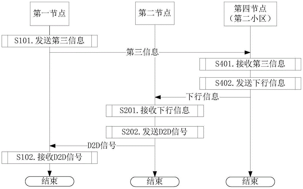
[0111] Embodiment 2 illustrates the flow chart of establishing a D2D connection, as shown in the attached figure 2 shown.
[0112] for first node , the third information is sent in step S101, and the D2D signal is received in step S102.
[0113] for fourth node , receiving third information in step S401, and sending downlink information in step S402.
[0114] for second node , receiving the downlink information in step S201, and sending a D2D signal in step S202.
[0115] In Embodiment 2, the third information includes {identity of the first node, measurement result of the first node for the second cell, moving speed of the first node, moving direction of the first node, measurement result of the second node} at least one of the . The downlink information instructs the first node to maintain the RRC connection with the second cell through the relay of the second node.
[0116] As a sub-embodiment 1 of Embodiment 2, the D2D signal includes {the downlink information, ...
Embodiment 3
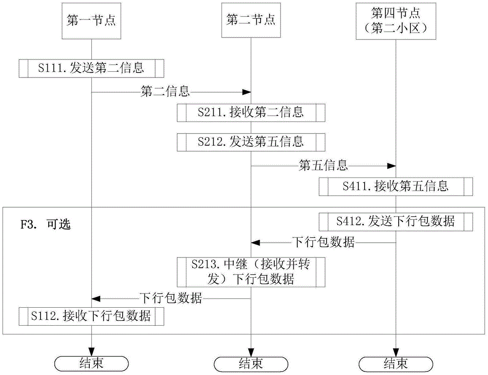
[0118] Embodiment 3 illustrates the flow chart of the second node relaying downlink data packets, as shown in the attached image 3 shown. The step of downlink relay described in block F3 is optional.
[0119] For the first node, the second information is sent in step S111, and the downlink packet data is received in step S112.
[0120] For the second node, the second information is received in step S211, the fifth information is sent in step S212, and the downlink packet data is relayed (received and sent) in step S213.
[0121] For the fourth node, the fifth information is received in step S411, and the downlink packet data is sent in step S412.
[0122] In Embodiment 3, the second information includes all or part of fields in {RLF-Report-r9, RLF-Report-v9e0}. The second information includes an identifier of the second cell, the second cell is maintained by the fourth node, and the second cell is a serving cell of the second node.
[0123] The essence of Embodiment 3 is ...
PUM
 Abstract
Description
Claims
Application Information
 - R&D
- Intellectual Property
- Life Sciences
- Materials
- Tech Scout
- Unparalleled Data Quality
- Higher Quality Content
- 60% Fewer Hallucinations
Browse by: Latest US Patents, China's latest patents, Technical Efficacy Thesaurus, Application Domain, Technology Topic, Popular Technical Reports.
© 2025 PatSnap. All rights reserved.Legal|Privacy policy|Modern Slavery Act Transparency Statement|Sitemap|About US| Contact US: help@patsnap.com


