
Reverse osmosis membrane element and water purifying device

A technology of reverse osmosis membranes and elements, applied in the field of reverse osmosis membrane elements and water purification devices, can solve the problems of serious concentration polarization at the inlet end, low water flow velocity, large back pressure, etc., so as to improve the pure water flux and The effect of desalination rate, smooth discharge of pure water, and improved service life

Pending Publication Date: 2017-03-08
GREE ELECTRIC APPLIANCES INC
View PDF9 Cites 9 Cited by
  • Summary
  • Abstract
  • Description
  • Claims
  • Application Information

AI Technical Summary

Problems solved by technology

The reverse osmosis membrane element of this structure has the following problems: (1) The raw water flow channel is long, and there is a transition area where the water flow in the raw water flow channel is from the inlet to the concentrated water outlet, and there is an area with extremely low water flow velocity, and the end of the reverse osmosis membrane element There is serious pollution, resulting in a rapid decline in the performance of reverse osmosis membrane elements
(2) The inlet flow channel is small, the pollutants are not easy to wash away, and the reverse osmosis membrane elements cannot be effectively washed
(3) The concentrated water end of the reverse osmosis membrane element is seriously polarized relative to the concentration difference at the water inlet end, and the concentrated water end is seriously polluted
(4) The pure water is collected through the central tube, the resistance is relatively large, the back pressure in the pure water channel is relatively large, and the water production efficiency is low

Method used


Image

  • Reverse osmosis membrane element and water purifying device
  • Reverse osmosis membrane element and water purifying device
  • Reverse osmosis membrane element and water purifying device

Examples


Embodiment Construction

[0023] In order to make the above objects, features and advantages of the present invention more comprehensible, specific implementations of the present invention will be described in detail below in conjunction with the accompanying drawings. In the following description, numerous specific details are set forth in order to provide a thorough understanding of the present invention. However, the present invention can be implemented in many other ways different from those described here, and those skilled in the art can make similar improvements without departing from the connotation of the present invention, so the present invention is not limited by the specific implementations disclosed below.

[0024] It should be noted that when an element is referred to as being “fixed on” or “disposed on” another element, it may be directly on the other element or there may be an intervening element. When an element is referred to as being "connected to" another element, it can be directl...


PUM

PropertyMeasurementUnit
thicknessaaaaaaaaaa

Abstract

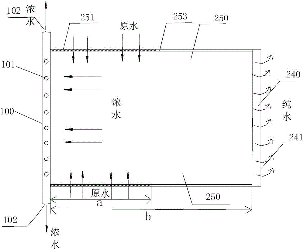
A reverse osmosis membrane element comprises a central tube and a reverse osmosis membrane assembly wound on the central tube, wherein the reverse osmosis membrane assembly comprises a water inlet separating net, a pure water guide net and reverse osmosis membranes; a pure water flow path is formed between the front interlayers of the reverse osmosis membranes; a water inlet flow path is formed between the reverse interlayers of the reverse osmosis membranes; the water inlet separating net is positioned in the water inlet flow path; the pure water guide net is positioned in the pure water flow path; a plurality of concentrated water inlets are formed in the central tube; the end of the central tube is used as a concentrated water outlet of the reverse osmosis membrane element; the reverse osmosis membrane element is provided with two water inlets; the two water inlets are respectively positioned in two end surfaces of the reverse osmosis membrane element; the pure water inlet of the reverse osmosis membrane element is positioned in the circumferential surface of the reverse osmosis membrane element. The reverse osmosis membrane element has the advantages that the pollution speed of the reverse osmosis membrane element can be reduced effectively, the service life of the reverse osmosis membrane element is prolonged, and meanwhile, water production efficiency is improved. The invention further provides a water purifying device.

Description

technical field [0001] The invention relates to the field of water purification systems, in particular to a reverse osmosis membrane element and a water purification device. Background technique [0002] see figure 1 , the working principle of the existing reverse osmosis membrane elements is that the direction of the raw water inlet and concentrated water outflow is parallel to the central tube, and the direction of the product water outflow is perpendicular to the central tube. By sealing the three sides of the membrane bag away from the central tube, the Realize the separation of raw water, concentrated water and pure water. The reverse osmosis membrane element of this structure has the following problems: (1) The raw water flow channel is long, and there is a transition area where the water flow in the raw water flow channel is from the inlet to the concentrated water outlet, and there is an area with extremely low water flow velocity, and the end of the reverse osmosis...

Claims


Application Information

Patent Timeline
Patent Type & Authority Applications(China)
IPC IPC(8): B01D61/08B01D63/06C02F1/44
CPCB01D61/025B01D61/08B01D63/065C02F1/441B01D2315/12B01D2313/23B01D2311/16
Inventor 李一然秦利利周栋杨勇张量
Owner GREE ELECTRIC APPLIANCES INC
Learn More