Cap milling clamp used for crankshaft connecting rod production

A crankshaft connecting rod and cover clamping technology, which is applied in clamping, clamping devices, manufacturing tools, etc., can solve the problems of low processing efficiency, inconvenient removal of parts after clamping, and high labor intensity of workers, so as to improve processing efficiency and reduce The effect of labor intensity and convenient clamping

Inactive Publication Date: 2017-03-08
重庆昌跃机电制造有限公司
View PDF12 Cites 2 Cited by
  • Summary
  • Abstract
  • Description
  • Claims
  • Application Information

AI Technical Summary

Problems solved by technology

When milling the connecting rod cover, it is necessary to fix the connecting rod cover on the milling machine first, and then perform milling treatment on it. In the existing milling equipment, the fixing device of the connecting rod cover can only clamp one at a time. The processing efficiency of the workpiece is low, and it is very inconvenient to pick up the workpiece immediately after clamping, resulting in high labor intensity for workers and high labor costs

Method used


Image

  • Cap milling clamp used for crankshaft connecting rod production
  • Cap milling clamp used for crankshaft connecting rod production
  • Cap milling clamp used for crankshaft connecting rod production

Examples


Embodiment Construction

[0021] The technical solutions in the present invention will be further described below in conjunction with the accompanying drawings and embodiments.

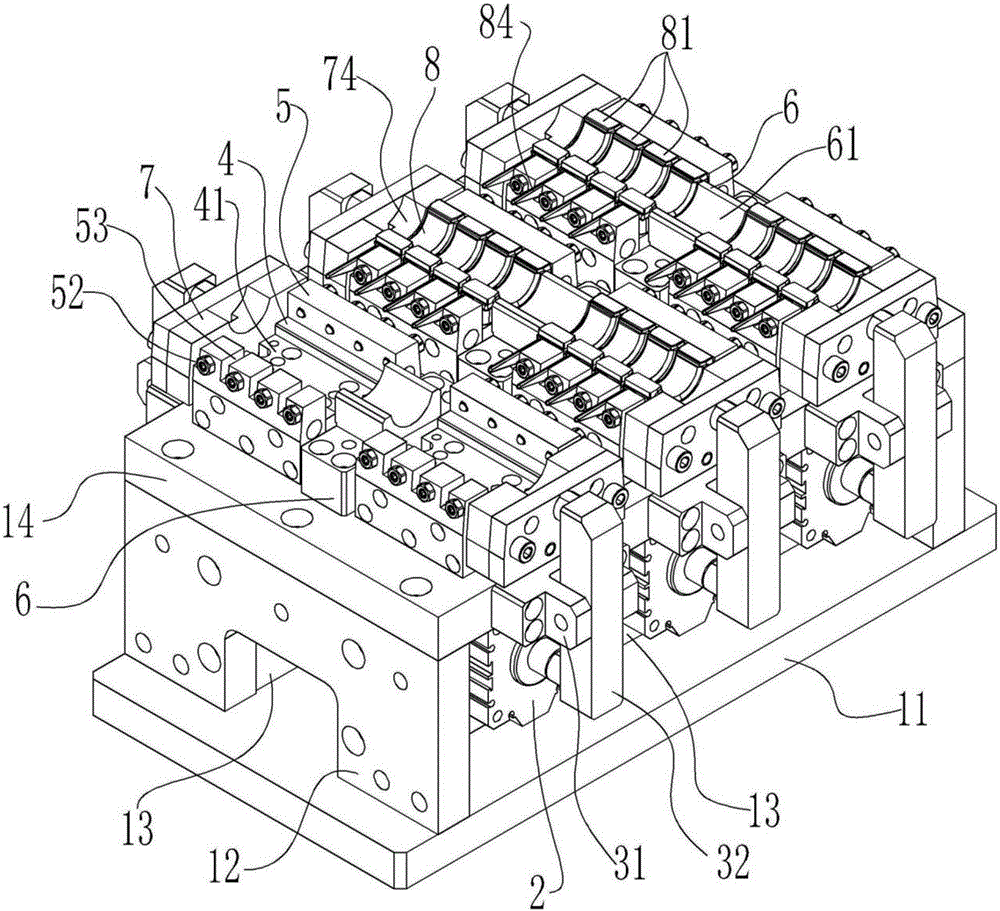
[0022] As shown in the figure, the present invention proposes a milling fixture for crankshaft connecting rod production, including:

[0023] Roughly rectangular parallelepiped mounts, such as figure 1 As shown, the mounting seat includes a horizontal bottom plate 11, two wide-side side plates 12 and two long-side side plates 13 vertically fixed on the bottom plate 11, and a top plate 14 fixed on the upper end of the wide-side side plate 12, two The wide-side side plate 12 and two long-side side plates 13 surround a cuboid structure and the long-side side plate 13 is set in a sunken type, and the top plate 14 and the long-side side plate 14 are all provided with mounting screw holes;

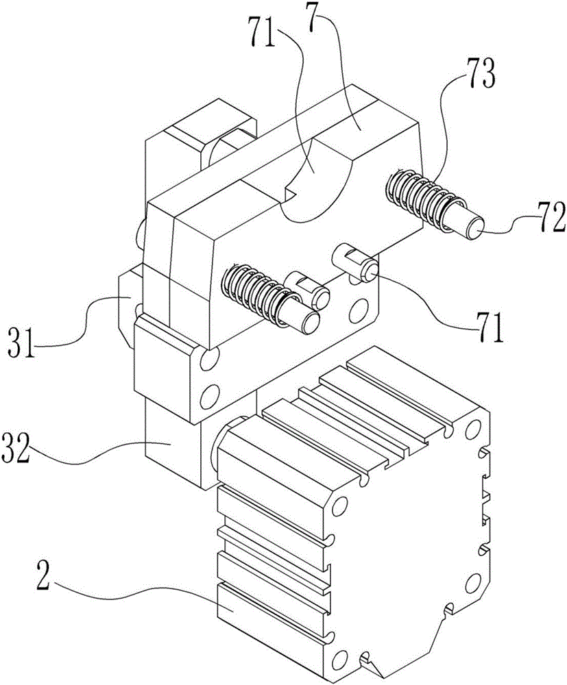
[0024] Many pairs of lever mechanisms that are symmetrically arranged on the two opposite side walls of the top plate 14 and the cylinders 2 t...


PUM


Abstract

The invention provides a cap milling clamp used for crankshaft connecting rod production. The cap milling clamp comprises a mounting base, a plurality of pairs of lever mechanisms, air cylinders and a clamping device. The pairs of lever mechanisms and the air cylinders are symmetrically arranged on the two side walls of the mounting base. The lower ends of levers are located on the extension lines of air cylinder spindles. The clamping device is arranged on the mounting base and comprises bases, side clamping plates, fixed clamping plates and movable clamping plates. The multiple bases are in linear arrangement, and the upper surfaces of the bases are provided with grooves. The side walls, perpendicular to the direction of the air cylinder spindles, of the bases are provided with first guide holes. The side clamping plates are arranged at the two sides of the corresponding bases. The side walls of the side clamping plates are provided with second guide holes, and the second guide holes are stepped holes. The side clamping plates are further provided with screws, and the fixed clamping plates are arranged between the adjacent bases located in the same linear arrangement. The movable clamping plates are arranged between the upper ends of the levers and the adjacent bases. One sides of the movable clamping plates are provided with first guide rods inserted into the first guide holes and second guide rods inserted into the second guide holes. The second guide rods are sleeved with compression springs. According to the cap milling clamp used for crankshaft connecting rod production, clamping is convenient, and machining efficiency is improved.

Description

technical field [0001] The invention relates to the field of mechanical manufacturing, in particular to a tool for producing crankshaft connecting rods. Background technique [0002] Crankshaft-connecting rod mechanism is a transmission mechanism widely used in engines and motors. It is used to realize the power transmission between the linear reciprocating motion of the piston and the rotary motion of the crankshaft. The connecting rod is a rod-shaped rod directly connected between the piston and the crankshaft. The structure generally includes a small end, a shaft and a large end. The small end of the connecting rod is used to connect the piston pin, the large end of the connecting rod is used to connect with the crank pin of the crankshaft, and the shaft is used to connect the small end and the large end. The big head is designed as a split type, and the separated part is the connecting rod cover. During production, the connecting rod and the connecting rod cover are die-...

Claims


Application Information

Patent Timeline
IPC IPC(8): B23Q3/08
CPCB23Q3/061B23Q3/082B23Q2703/105
Inventor 温昌明张跃
Owner 重庆昌跃机电制造有限公司
Why Eureka
Try Eureka