Automatic cooling control system for machine tool

A technology of automatic cooling and control system, applied in the direction of manufacturing tools, metal processing machinery parts, maintenance and safety accessories, etc., can solve problems such as hindering the use and development of coolant regulation technology and complicating coolant regulation methods.

Inactive Publication Date: 2017-03-08
张武昌
View PDF6 Cites 7 Cited by
  • Summary
  • Abstract
  • Description
  • Claims
  • Application Information

AI Technical Summary

Problems solved by technology

However, during the use of the coolant, the temperature changes are complicated, and the heating and cooling processes are often entangled with each other, which makes it necessary to consider many factors such as the temperature change and flow rate change of the coolant during the control process, which leads to the complexity of the coolant control method. Even Special personnel are required to operate the use of coolant, which greatly hinders the use and development of control technology in the process of coolant spraying

Method used


Image

  • Automatic cooling control system for machine tool

Examples


Embodiment Construction

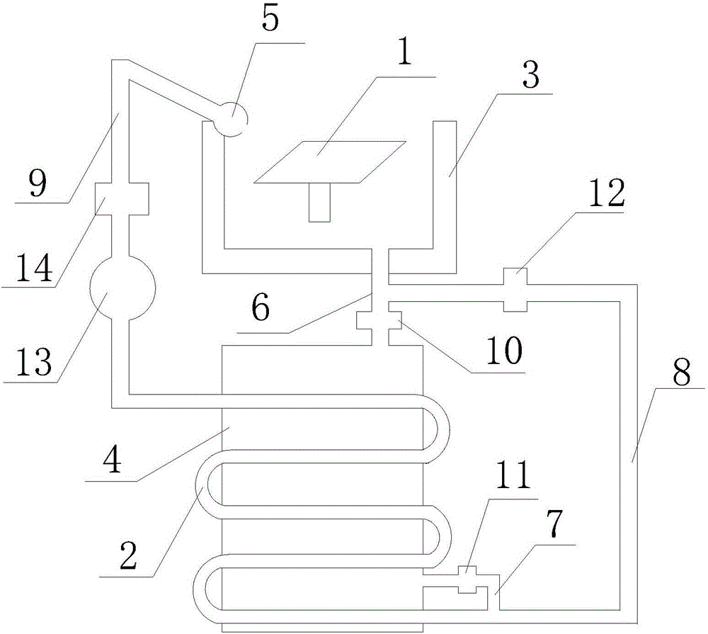
[0015] Such as figure 1 as shown, figure 1 It is a machine tool automatic cooling control system proposed by the present invention.

[0016] refer to figure 1 , the machine tool automatic cooling control system proposed by the present invention includes a workbench 1, a circulation pipeline 2, a refrigeration device, a liquid accumulation tank 3, a cooling tank 4, a coolant nozzle 5 and a controller;

[0017] There is a processing station on the workbench 1; the top of the liquid accumulation tank 3 is open, and the liquid accumulation tank 3 is located under the workbench 1 and collects the liquid generated during the cooling process; the bottom of the liquid accumulation tank 3 is provided with a first liquid outlet; the cooling tank 4 The liquid inlet communicates with the first liquid outlet through the first pipeline 6, the liquid outlet of the cooling box 4 communicates with the first end of the circulation pipeline 2 through the second pipeline 7, and the first liquid...


PUM


Abstract

The invention discloses an automatic cooling control system for a machine tool. The automatic cooling control system comprises a worktable, a circulating pipeline, a refrigeration device, a liquid storing tank, a cooling tank, a coolant spray head and a controller, a first throttling valve, a second throttling valve and a third throttling valve are separately arranged on a first pipeline, a second pipeline and a third pipeline; a flow pump and a flowmeter are arranged on a fourth pipeline; the flowmeter is positioned between the flow pump and the coolant spray head; a first temperature detector is arranged at the coolant spray head; a first cooling mode, a second cooling mode and a third cooling mode are preset for the controller; the controller acquires a first temperature detection value T1 through a first temperature sensor and acquires flow speed information V through the flowmeter; the controller controls the flow pump to adjust the flow speed according to the flow speed information V; an ideal temperature interval [t1,t2] is preset for the controller; if T1 is greater than or equal to the t1 and smaller than or equal to the t2, the controller adopts the second cooling mode; if the lt is greater than or equal to the T1 and smaller than or equal to the t1, the controller adopts the first cooling mode; and if gt is greater than or equal to the T1 and smaller than or equal to the t2, the controller adopts the third cooling mode.

Description

technical field [0001] The invention relates to the technical field of automatic temperature reduction, in particular to an automatic temperature reduction control system for machine tools. Background technique [0002] A machine tool is a machine that processes metal blanks into mechanical parts. Due to frequent cutting, extrusion and friction between the workpiece and the processing tool, the temperature of the processing tool and the workpiece is very high. When the temperature at the processing place is too high, it will The machining of the workpiece causes damage and affects the hardness of the tool, resulting in a decrease in machining accuracy and damage to the tool. At this time, it is necessary to cool down the processing place. At present, liquid spray pipes are usually used to spray the processing part to cool the processing tool and the workpiece. Some machine tools use coolant with lubricating effect, so that during the cooling process, the processing tool and ...

Claims


Application Information

Patent Timeline
Patent Type & Authority Applications(China)
IPC IPC(8): B23Q11/10
CPCB23Q11/1053
Inventor 张武昌
Owner 张武昌
Why Eureka
Try Eureka