Laundry Drying Device With A Door Lint Filter Seat And Method For Producing The Same

A technology of fluff and utensils, which is applied in the field of clothes drying utensils, can solve the problems of high development and manufacturing costs, and achieve the effects of reduced development costs and simple manufacturing

Active Publication Date: 2017-03-08
BSH BOSCH & SIEMENS HAUSGERAETE GMBH
View PDF7 Cites 2 Cited by
  • Summary
  • Abstract
  • Description
  • Claims
  • Application Information

AI Technical Summary

Problems solved by technology

[0007] A disadvantage of these known laundry drying appliances is the high development and production co

Method used


Image

  • Laundry Drying Device With A Door Lint Filter Seat And Method For Producing The Same
  • Laundry Drying Device With A Door Lint Filter Seat And Method For Producing The Same
  • Laundry Drying Device With A Door Lint Filter Seat And Method For Producing The Same

Examples


Embodiment Construction

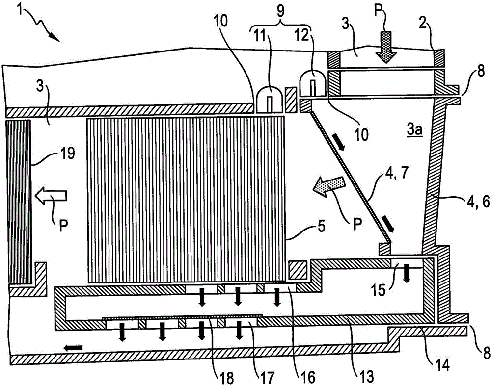
[0058] figure 1 A section of a laundry drying appliance in the form of a laundry dryer 1 according to a first exemplary embodiment is shown in side view as a sectional view. The laundry dryer 1 is produced in such a way that a first element in the form of an adapter (top figure) is inserted into the door lint filter holder 2 in the process air channel 3 . The process air P flowing out of the laundry drum (above) is guided essentially without effect through the adapter. The adapter can be designed in such a way that it prevents laundry from flooding into the process air channel 3 , for example, in that the adapter has a grill on the upper side.

[0059] Behind the adapter, the process air P flows into the region 3 a of the process air duct 3 , which is closed at the front by the cover 4 and abuts against the first heat exchanger 5 at the rear. The cover 4 has an actual cover part 6 for closing the process air channel 3 at the front, and a fluff screen 7 connected to it on the...


PUM


Abstract

The invention provides a method for producing a laundry drying device 1. A first element is inserted into a door lint filter 2 which is from loading opening of a laundry drum into a process air channel 3, a second element 9 is inserted into a diffuser seat 10 in a wall of the process air channel, at least partially of the diffuser seat 10 is above a first heat exchanger 5, a third element 13 is below the first heat exchanger and is inserted into a base seat 14, and a fourth element 4 in the form of a front-side cover 6 is inserted in a cover seat 8, and the front-side cover 6 is used as a wall of the process air channle, wherein the first to fourth elements 4, 9, 13 are selected from respective first to fourth elements, the plurality of elements of a set are constructred for inserting in their respective seats 2, 4, 8, 14, and the plurality of elements of a set are functionally differently configured. The invention also relates to a laundry dryer produced by the method.

Description

technical field [0001] The invention relates to a method for producing a laundry drying appliance with a door fluff sieve seat. The invention also relates to a laundry drying appliance produced in this way. The invention can be used particularly advantageously in domestic laundry dryers with heat pumps. Background technique [0002] Laundry drying appliances are known which have an internally closed process air channel which has at least one heat exchanger (hereinafter referred to generally as "first heat exchanger" without limitation) and serves to cool the process air . The water vapor in the process air arriving there, which previously flowed out of the laundry drum as wet process air, condenses on the cold surface of the first heat exchanger and then in the form of droplets as condensed water Fall from it. The wet process air discharged by the laundry drum also contains hair, fluff etc., which can partly deposit on the wet first heat exchanger and thus reduce its eff...

Claims


Application Information

Patent Timeline
IPC IPC(8): D06F58/10D06F58/22D06F58/20
CPCD06F58/22D06F58/24
Inventor R·伯梅尔斯O·德斯庞H·亨尼希M·舒伯特A·蒂姆勒
Owner BSH BOSCH & SIEMENS HAUSGERAETE GMBH
Why Eureka
Try Eureka