Supercharge Your Innovation With Domain-Expert AI Agents!

Low torque natural gas fixed ball valve

A technology for fixing ball valves and natural gas, applied in valve details, valve devices, valve shell structures, etc., can solve problems such as insufficient internal structure, complex structure of fixed ball valves, increased valve stem torque, etc., to achieve convenient operation and production The effect of creating and reducing torque force

Inactive Publication Date: 2017-03-08
ZHEJIANG BIAOSHENG VALVE MFG CO LTD
View PDF4 Cites 0 Cited by
  • Summary
  • Abstract
  • Description
  • Claims
  • Application Information

AI Technical Summary

Problems solved by technology

The traditional trunnion ball valve consists of a valve body, a valve core and a valve stem. The inside of the body is connected by the lower bottom shaft. There are the following defects in the fixed ball valve with this structure: First, because the valve stem directly bears the thrust of the valve core, the valve stem not only bears the torque of the valve stem itself during the switching process, It also needs to withstand the thrust from the fluid, so that the torque of the valve stem increases during the switching process, which is not conducive to the switching operation; The structure is not compact enough, so it is prone to leakage; third, the existing fixed ball valve has a complex structure, which is not conducive to growth in production and increases production costs

Method used


Image

  • Low torque natural gas fixed ball valve

Examples


Embodiment Construction

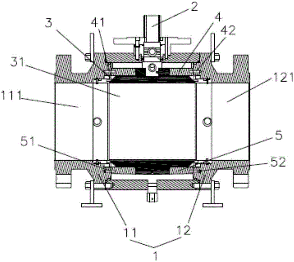
[0014] Such as figure 1 As shown, a low-torque natural gas fixed ball valve includes a valve body 1 and a valve stem 2. The valve body 1 is divided into a left valve body 11, an intermediate body 3 and a right valve body 12, between the left valve body 11 and the right valve body 12 Connected by the intermediate body 3, the left valve body 11 is provided with a left fluid channel 111, the right valve body 12 is provided with a right fluid channel 121, and the intermediate body 3 is provided with a middle fluid channel 31, the middle fluid channel 31, left The diameters of the fluid channel 111 and the right fluid channel 121 are the same, and the design is beneficial to reduce the thrust from the fluid, thereby reducing the torque force, and facilitating people's operation. The middle fluid channel 31 of the intermediate body 3 rotates when the intermediate body 3 rotates. The left fluid passage 111 of the left valve body 11 and the right fluid passage 121 of the right valve bo...


PUM


Abstract

The invention discloses a low torque natural gas fixed ball valve. The low torque natural gas fixed ball valve comprises valve bodies and a valve rod; the valve bodies divided into the left valve body, an intermediate body and the right valve body; the left valve body and the right valve body are connected through the intermediate body; the left valve body is provided with a left fluid channel; the right valve body is provided with a right fluid channel; the intermediate body is provided with a middle fluid channel; the upper end face of a valve element is provided with an upper supporting block; one end of the upper supporting block is connected with the inner wall of the upper portion of the left valve body; the other end of the upper supporting block is connected with the inner wall of the upper portion of the right valve body; the middle of the upper supporting block is provided with a valve rod hole; the valve rod penetrates the valve rod hole of the upper supporting block; the lower end of the valve rod is connected with the intermediate body; the upper end of the valve rod extends upwards to go out from the interiors of the valve bodies; the lower end face of the intermediate body is provided with a lower supporting block; one end of the lower supporting block is connected with the inner wall of the lower portion of the left valve body; and the other end of the lower supporting block is connected with the inner wall of the lower portion of the right valve body. The low torque natural gas fixed ball valve is reasonable in design, simple in structure, convenient to produce and manufacture and capable of relieving the torque and reducing leakage at the same time.

Description

Technical field [0001] The invention relates to the technical field of ball valves, in particular to a low-torque natural gas fixed ball valve. Background technique [0002] A ball valve is a valve with a valve stem that drives the opening and closing parts (ball core) and rotates 90 degrees around the axis of the valve stem. It is mainly used for fluid adjustment and control. Ball valves are generally divided into floating ball valves and fixed ball valves. The fixed ball valve is a new generation of high-performance ball valve, suitable for long-distance pipelines and general industrial pipelines. Its strength, safety, and harsh environment resistance are specially considered in the design, and it is suitable for various corrosive and non-corrosive media. The traditional fixed ball valve includes a valve body, a valve core and a valve stem. The upper end of the valve core is connected with the inner wall of the valve body through a drive shaft. The valve stem extends through th...

Claims


Application Information

Patent Timeline
Patent Type & Authority Applications(China)
IPC IPC(8): F16K5/06F16K27/06
CPCF16K5/06F16K5/0647F16K27/067
Inventor 梁世添田宏周梁世森
Owner ZHEJIANG BIAOSHENG VALVE MFG CO LTD
Features
  • R&D
  • Intellectual Property
  • Life Sciences
  • Materials
  • Tech Scout
  • Unparalleled Data Quality
  • Higher Quality Content
  • 60% Fewer Hallucinations
Learn More