Signal receiving device and three-dimensional spatial positioning system
A signal receiving device and signal receiving technology, applied in the field of positioning, can solve problems such as complex equipment configuration, insufficient positioning accuracy, and unsatisfactory conditions, and achieve the effects of expanding application scenarios, high positioning accuracy, and low cost
- Summary
- Abstract
- Description
- Claims
- Application Information
AI Technical Summary
Problems solved by technology
Method used
Image
Examples
Embodiment 1
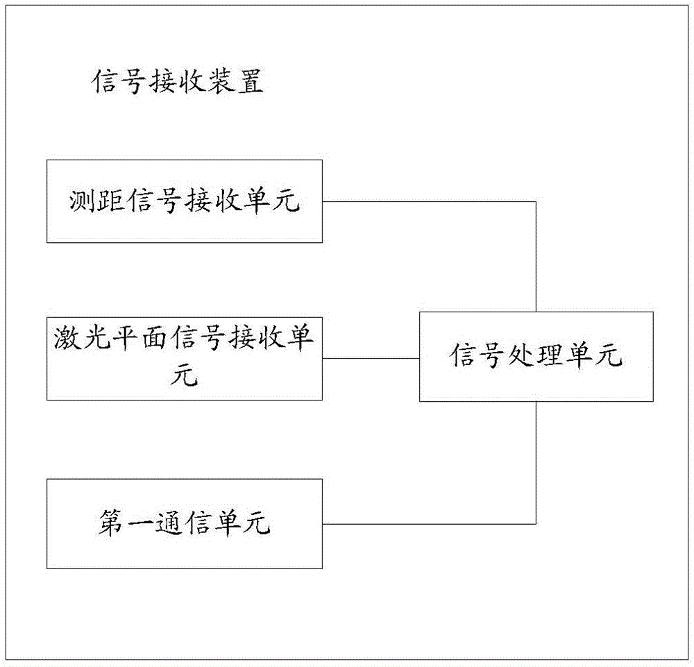
[0044] The signal receiving device provided in this embodiment is used in conjunction with the signal sending device. The signal sending device is used to send the ranging signal, rotate around the first rotation axis to send the first laser plane signal, and rotate around the second rotation axis to send the second laser plane signal. Laser plane signal.
[0045] It should be noted that the plane defined by the first rotation axis and the second rotation axis includes the following situations: when the first rotation axis and the second rotation axis can intersect in a plane, the plane defined by the first rotation axis and the second rotation axis The determined plane is the uniquely determined plane of the first rotation axis and the second rotation axis; when the first rotation axis and the second rotation axis cannot intersect in a plane, the plane determined by the first rotation axis and the second rotation axis Refers to a pair of parallel planes defined by the first r...
Embodiment 2
[0098] Such as image 3 As shown, the three-dimensional space positioning system of this embodiment includes: a signal receiving device and a signal sending device. The signal sending device is used as a reference coordinate base point for three-dimensional space positioning, and the signal receiving device is used as a point to be positioned.
[0099] Among them, the signal sending device is used to send the ranging signal to the signal receiving device, rotate around the first rotation axis to send the first laser plane signal, and rotate around the second rotation axis to send the second laser plane signal; the signal receiving device is used to detect The ranging signal, the first laser plane signal and the second laser plane signal. Preferably, the signal sending device is also used to send a time synchronization signal to the signal receiving device, and the signal receiving device is also used to receive the time synchronization signal from the signal sending device, s...
example 1
[0125]For example, the first reference angle and the second reference angle are both 0, that is, at the first reference moment (or the second reference moment), the laser plane signal sent by the rotating laser plane transmitter A (or B) is relative to the first position of the XOY plane. The reference angle α' is 0. Wherein, the rotational speeds of the rotating laser plane emitters A and B can be the same.
[0126] Among them, when the rotating laser plane transmitter A (or B) of the positioning base station rotates to the first reference angle (or the second reference angle) to send the laser plane signal each time, the positioning base station will pass through the second communication unit (such as a radio communication circuit) ) to send the first reference moment (or the second reference moment) to the marking device to be positioned.
[0127] Herein, refer to Figure 4 , when the first reference angle is 0 (that is, the angle between the rotation plane S1 and the XOY...
PUM
 Abstract
Description
Claims
Application Information
 - R&D
- Intellectual Property
- Life Sciences
- Materials
- Tech Scout
- Unparalleled Data Quality
- Higher Quality Content
- 60% Fewer Hallucinations
Browse by: Latest US Patents, China's latest patents, Technical Efficacy Thesaurus, Application Domain, Technology Topic, Popular Technical Reports.
© 2025 PatSnap. All rights reserved.Legal|Privacy policy|Modern Slavery Act Transparency Statement|Sitemap|About US| Contact US: help@patsnap.com


