Apartment rendering drawing method and device

A technology of floor plans and equipment, which is applied in the field of surveying and mapping, can solve the problems of rough drawing of floor plans, distortion of floor plans, lack of floor plans, etc., and achieve the effect of simplifying the process of drawing floor plans, high accuracy and high efficiency

Active Publication Date: 2017-03-08
杭州上柏建筑设计咨询有限公司
View PDF6 Cites 13 Cited by
  • Summary
  • Abstract
  • Description
  • Claims
  • Application Information

AI Technical Summary

Problems solved by technology

[0008] The purpose of the present invention is to provide a method for automatically drawing a house type map and further provide an intelligent device for implementing th...

Method used


Image

  • Apartment rendering drawing method and device
  • Apartment rendering drawing method and device

Examples


Embodiment 1

[0057] A method for drawing a floor plan in this embodiment comprises the following steps:

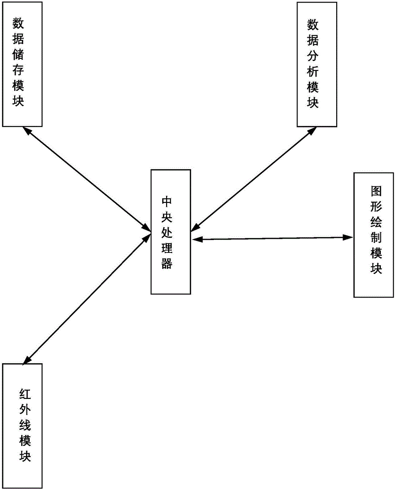
[0058] Step S1, select a test base point in the room, the near-infrared sensor rotates at a constant speed at the test base point, and further the near-infrared sensor rotates at a uniform speed of 360 degrees at the test base point, and sets the test interval angle r, and every time an angle r is rotated, Record the current test angle R and test distance (the distance from the test base point to the wall) L once, draw the outline endpoint P according to the current test angle R and test distance L in the drawing template, and connect all the outline endpoints P1-Pn to draw the preliminary apartment type of the room picture.

[0059] Step S2, door location identification: identify the jump of the outline of the floor plan, when the difference L'=|Ln-L(n+1)| between two adjacent test distances Ln and L(n+1) is greater than the set door When the limit is T1, it is judged as a contour ju...

Embodiment 2

[0063] A method and device for drawing a floor plan, comprising the following steps:

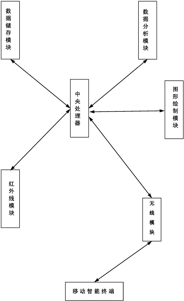
[0064] Step S1, select a test base point in the room, the near-infrared sensor rotates at a constant speed at the test base point, and the further rotation angle can be 360 ​​degrees, set the test interval angle r, and record the current test angle R every time an angle r is rotated And the test distance (the distance from the test base point to the wall) L, draw the outline endpoint P according to the current test angle R and the test distance L in the drawing template, and connect all the outline endpoints P1-Pn to draw the preliminary floor plan of the room.

[0065] Step S2, door location identification: identify the jump of the outline of the floor plan, when the difference L'=|Ln-L(n+1)| between two adjacent test distances Ln and L(n+1) is greater than the set door When the limit is T1, it is judged as a contour jump, and the test distance minL(Ln, L(n+1)) of the smaller value is taken...

Embodiment 3

[0070] A method and device for drawing a floor plan, comprising the following steps:

[0071]Step S1, select a test base point in the room, the near-infrared sensor rotates at a constant speed at the test base point, and the further rotation angle can be 360 ​​degrees, set the test interval angle r, and record the current test angle R every time an angle r is rotated And the test distance (the distance from the test base point to the wall) L, draw the outline endpoint P according to the current test angle R and the test distance L in the drawing template, and connect all the outline endpoints P1-Pn to draw the preliminary floor plan of the room.

[0072] Step S2, door location identification: identify the jump of the outline of the floor plan, when the difference L'=|Ln-L(n+1)| between two adjacent test distances Ln and L(n+1) is greater than the set door When the limit is T1, it is judged as a contour jump, and the test distance minL(Ln, L(n+1)) of the smaller value is taken,...


PUM


Abstract

The invention belongs to the technical field of surveying and mapping and discloses an apartment rendering drawing method and device; the method comprises the steps of S1, drawing a single room rendering, to be specific, scanning a room with near infrared to obtain an initial rendering of the room; S2, recognizing a door position, to be specific, recognizing an outline hop of the rendering, removing the hopped outline, and marking out a doorway position and door width at the hop position; acquiring an inside-wall rendering of the room; S3, measuring wall thickness, to be specific, measuring wall thickness at the doorway with far infrared; S4, splicing rooms, to be specific, based on the doorway, using the wall thickness as spacing to splice renderings of adjacent rooms to obtain a complete rendering. By using the apartment rendering drawing method and device according to the technical scheme of the invention, it is possible to quickly acquire a rendering of a commercial apartment, the efficiency is high, the accuracy is high, and the distortion of apartment renderings is effectively avoided.

Description

technical field [0001] The invention belongs to the technical field of surveying and mapping, and relates to an automatic drawing technology of floor plans of commercial houses, in particular to a drawing method of floor plans of commercial houses based on infrared measurement technology and equipment for implementing the method. Background technique [0002] At present, second-hand housing transactions are relatively hot. Home decoration is essential. Many second-hand housing floor plans cannot be obtained. Designers need to manually measure, draw the final floor plan, and design. The existing manual drawing of floor plans is relatively inefficient. Work The amount is large, and a lot of labor costs are wasted. [0003] With the development of electronics and computer technology, automatic ranging technology has been developed rapidly. Laser ranging, microwave radar ranging, ultrasonic ranging, and infrared ranging technologies have emerged successively. Among them, laser ...

Claims


Application Information

Patent Timeline
IPC IPC(8): G06F17/50G01B11/06
CPCG01B11/06G06F30/13
Inventor 郭岳峰
Owner 杭州上柏建筑设计咨询有限公司
Why Eureka
Try Eureka