
Automatic recognition method at drainage network monitoring point

A drainage pipe network, automatic identification technology, applied in special data processing applications, instruments, electrical digital data processing, etc. Address national and industry needs, reduce manual workload, and ensure representative results

Active Publication Date: 2017-03-08
北京清控人居环境研究院有限公司 +1
View PDF5 Cites 21 Cited by
  • Summary
  • Abstract
  • Description
  • Claims
  • Application Information

AI Technical Summary

Problems solved by technology

[0004] (1) There is no uniform standard for the setting principles of drainage pipe network monitoring points. When monitoring drainage pipe networks in different regions and cities, the monitoring points may be arranged according to different principles, so that the obtained results cannot be objective Reflect the operation of the drainage network, lack of comparability
[0005] (2) Even if the monitoring points are arranged according to the similar principle, because it depends on the subjective judgment of the staff, there will be certain uncertainty, and it will consume a lot of manpower and time
[0006] (3) At present, the setting method of monitoring points is rarely simulated by the drainage system model, but the existing measured data is limited, especially the analysis of the differences in the rules of the pipe network nodes under different working conditions is lacking, so it can only be based on the understanding of the drainage rules Screen and set monitoring points when they are not comprehensive enough
[0007] (4) Although some setting methods use the drainage system model for simulation, they often perform certain screening first and only simulate a small number of nodes. This setting method has lost the information of some nodes and reduced the number of monitoring points. Representativeness and effectiveness under different working conditions

Method used


Image

  • Automatic recognition method at drainage network monitoring point
  • Automatic recognition method at drainage network monitoring point
  • Automatic recognition method at drainage network monitoring point

Examples


Embodiment Construction

[0035] Embodiments of the present invention are described in detail below, and examples of the embodiments are shown in the drawings, wherein the same or similar reference numerals denote the same or similar elements or elements having the same or similar functions throughout. The embodiments described below by referring to the figures are exemplary only for explaining the present invention and should not be construed as limiting the present invention.

[0036] These and other aspects of embodiments of the invention will become apparent with reference to the following description and drawings. In these descriptions and drawings, some specific implementations of the embodiments of the present invention are specifically disclosed to represent some ways of implementing the principles of the embodiments of the present invention, but it should be understood that the scope of the embodiments of the present invention is not limited by this limit. On the contrary, the embodiments of ...


PUM


Abstract

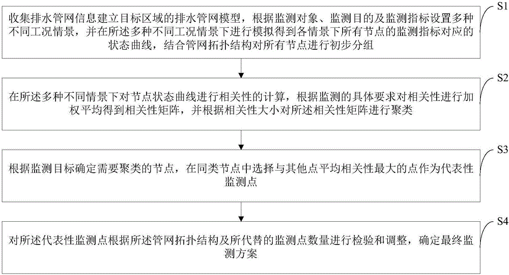
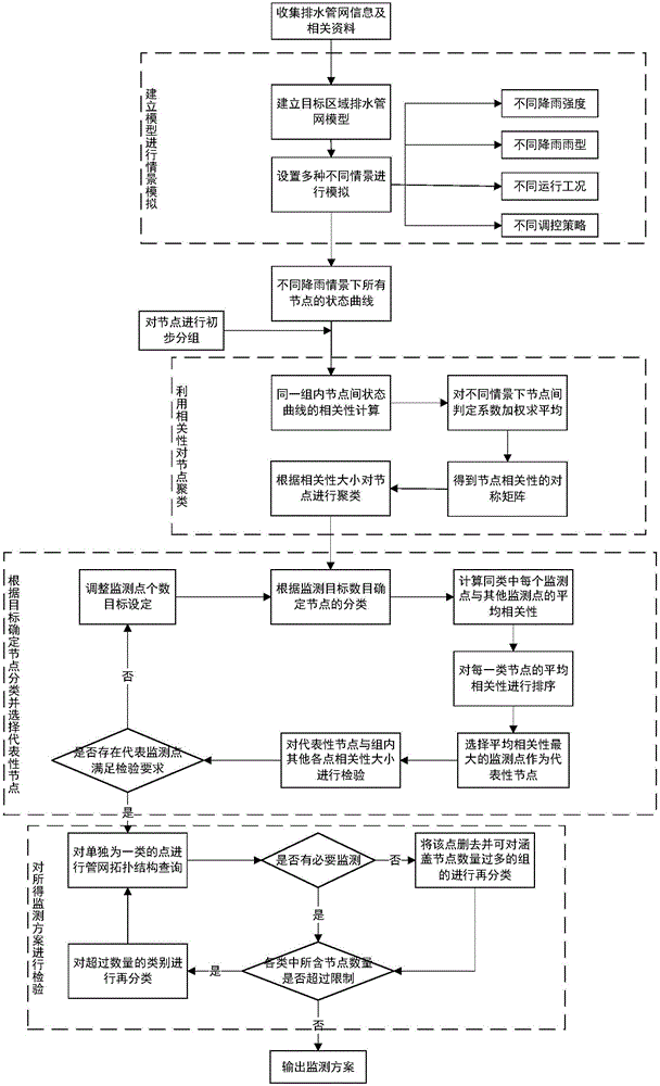
The invention discloses an automatic recognition method at a drainage network monitoring point. The method comprises the following steps: collecting information to establish a drainage network model at a target region, setting various scenario simulations to obtain status curves corresponding to all node monitoring indexes under each scenario, and initially grouping the nodes, computing the relevance among the node status curves, performing weighted average to obtain a relevant matrix, and clustering according to the relevancy size; selecting the point with the maximum average relevancy with other points in the same type of nodes as a representative monitoring point; checking and adjusting the representative monitoring point to determine a final monitoring scheme and to provide a quantified evaluation index about the good and bad of a monitoring scheme. The method disclosed by the invention has the following advantages that the limitation to the network operation law recognition is lowered when artificially making the scheme, the subjectivity of artificially setting the monitoring point is avoided, the artificial workload is reduced, the monitoring point representativeness is guaranteed, a quantified evaluation result of the monitoring scheme is provided, so that the operation status of the drainage network can be comprehensively reflected through less node monitoring.

Description

technical field [0001] The invention relates to the field of design and layout of urban water system monitoring points, and specifically designs a method for automatically identifying monitoring points of a drainage pipe network. Background technique [0002] For the performance evaluation of sponge city construction and the monitoring and evaluation of black and odorous water treatment, it is necessary to carry out quantitative evaluation based on actual monitoring data, and the monitoring of drainage pipe network is one of the key points. In the planning, management, evaluation and diagnosis of the drainage network, the support of real online monitoring data is needed. The reasonable arrangement of monitoring points can optimize the construction plan of the monitoring system, optimize the investment effect of the construction funds of the monitoring plan, and fully reflect the operation status of the entire drainage network through online monitoring data. However, there i...

Claims


Application Information

Patent Timeline
IPC IPC(8): G06F17/50
CPCG06F30/18G06F30/20
Inventor 郭效琛赵冬泉杜鹏飞王浩昌国小伟唐兰贵
Owner 北京清控人居环境研究院有限公司
Learn More