Relay

A technology of relays and insulating bottom plates, applied in the direction of relays, electromagnetic relays, detailed information of electromagnetic relays, etc., can solve the problems of poor internal insulation, reduce the service life of devices, increase the use of electrical components, etc., to improve reliability and The effect of safety, prolonging service life and saving installation space

Active Publication Date: 2017-03-08
BYD CO LTD
View PDF3 Cites 5 Cited by
  • Summary
  • Abstract
  • Description
  • Claims
  • Application Information

AI Technical Summary

Problems solved by technology

[0002] In the related art, the two connection contacts of the relay are electrically connected through a copper plate of a certain thickness. When the current in the external circuit is too large, since the relay has no overload protection function, the components of the load circuit are easily damaged, and the safety Furthermore, the relays in related technologies have no arc extinguishing function, and the internal insulation is not good. The low-voltage end components of the relay are prone to damage and breakdown, which greatly reduces the service life of the device.
[0003] In addition, during the use of the relay in the related art, additional protection devices, such as a separate fuse device, need to be added to the peripheral circuit where the relay is located. The separately assembled fuse device not only increases the use of electrical components in the circuit, but also requires Larger installation space

Method used


Image

  • Relay
  • Relay
  • Relay

Examples


Embodiment Construction

[0022] Embodiments of the invention are described in detail below, examples of which are illustrated in the accompanying drawings. The embodiments described below by referring to the figures are exemplary and are intended to explain the present invention and should not be construed as limiting the present invention.

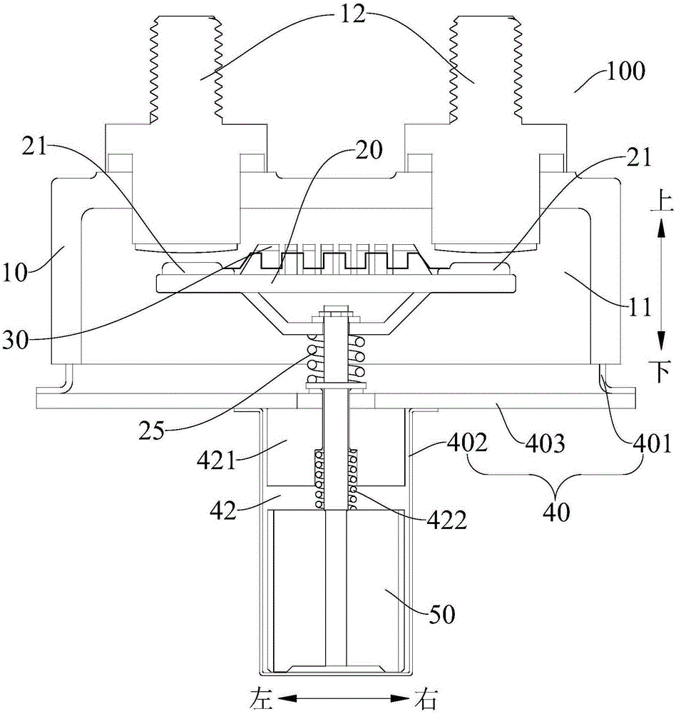
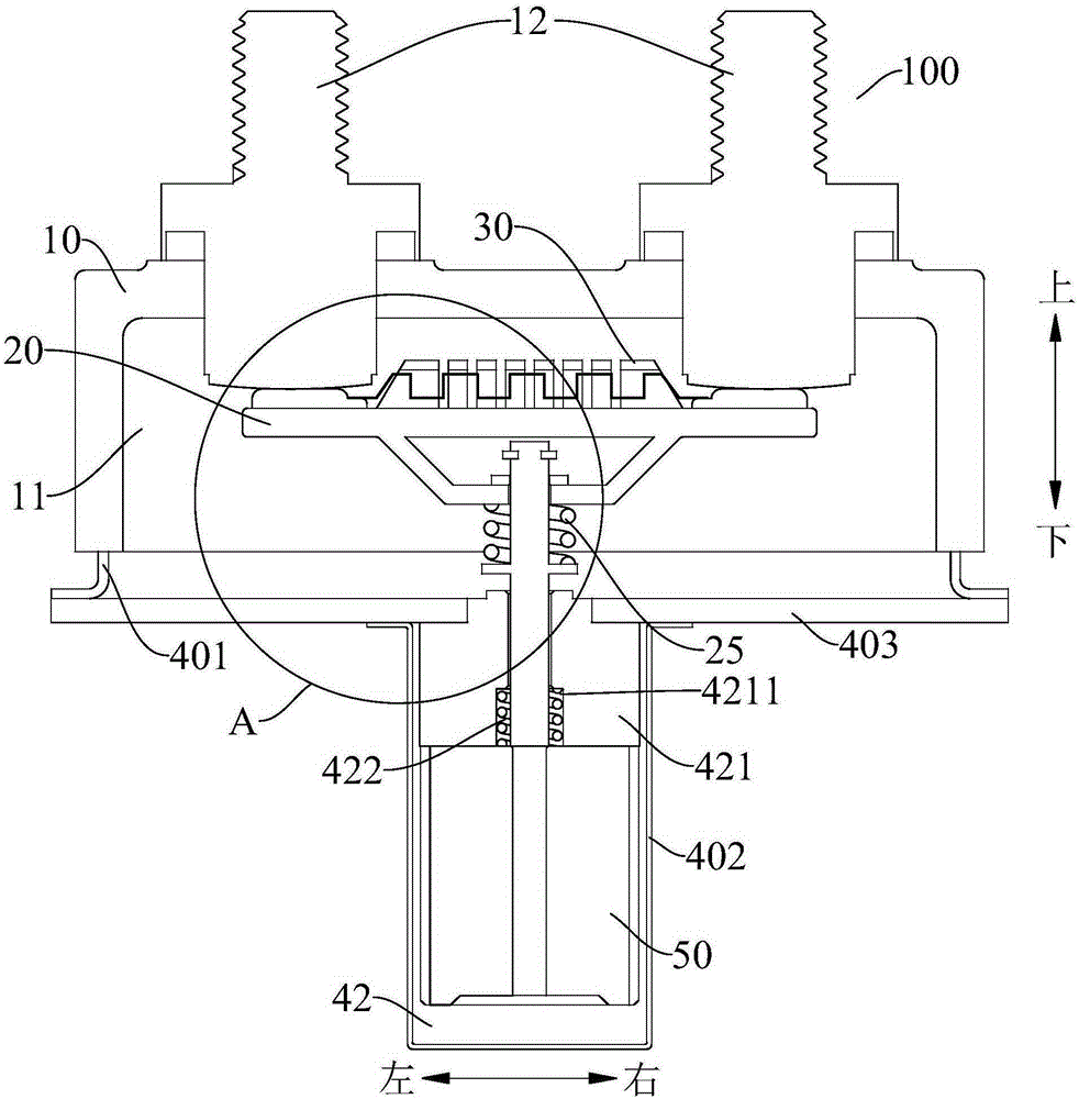
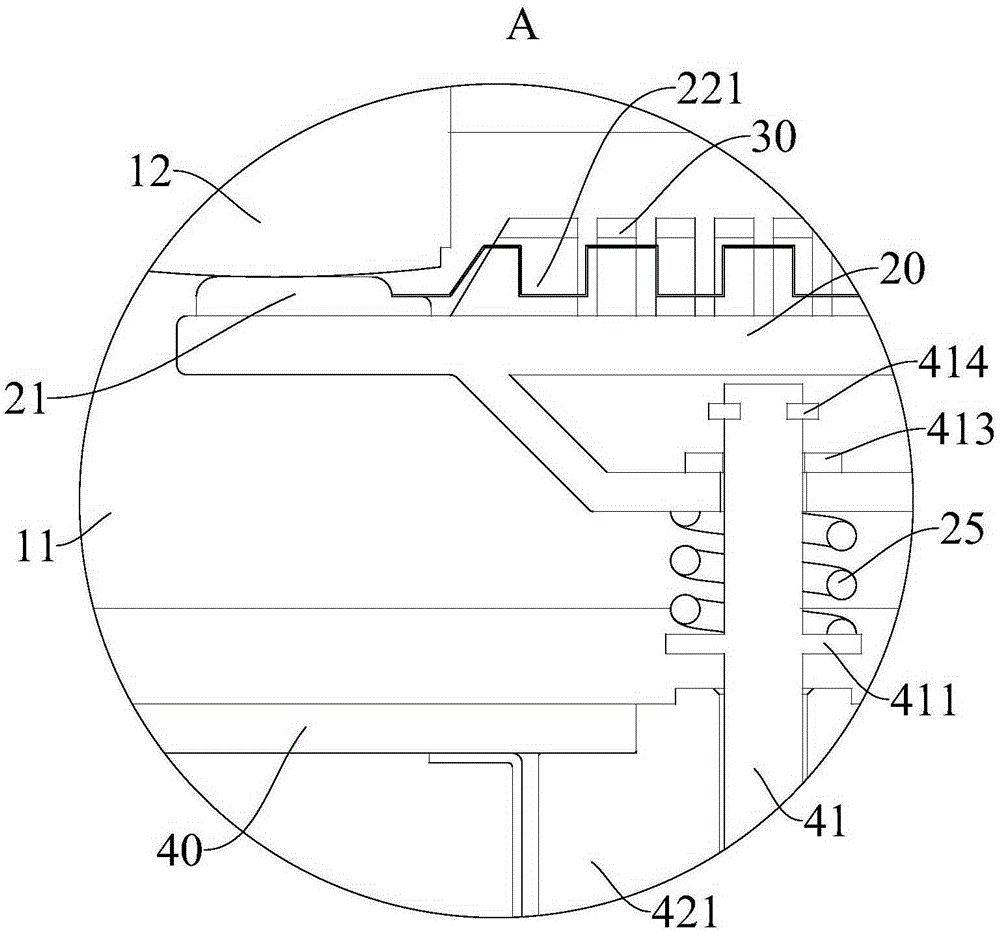
[0023] Attached below Figure 1 to Figure 7 The relay 100 according to the embodiment of the present invention will be described in detail.

[0024] The relay 100 according to the embodiment of the present invention includes an insulating case 10 , an insulating base 20 , a fuse 30 and a mounting base 40 . Specifically, an accommodating chamber 11 with an open end is defined in the insulating housing 10, and two terminal posts 12 arranged at intervals are arranged on the insulative housing 10, and one end of each terminal post 12 protrudes into the accommodating chamber 11. Bottom plate 20 is in first position (as figure 2 position status shown) and the secon...


PUM


Abstract

The invention discloses a relay which comprises an insulation shell, an insulation bottom plate, a fuse, and a mounting seat. A containing cavity with one open end is limited in the insulation shell. The insulation shell is provided with two separated wiring columns. The insulation bottom plate is movably arranged in the containing cavity between a first position and a second position. One side of the insulation bottom plate facing the wiring columns is provided with two separated connection contacts. When the insulation bottom plate is at the first position, each of the connection contact presses against a wiring column. When the insulation bottom plate is at the second position, the connection contacts are separated from the wiring columns. The fuse is arranged between the two connection contacts, and two ends of the fuse are electrically connected to the two connection contacts. The mounting seat is provided with a movable push rod to push the insulation bottom plate to move between the first position and the second position. According to the relay of the embodiment of the invention, the overload protection of an external circuit can be achieved, the burning and damage of the electrical components of the external circuit are avoided, and the reliability and the security of the system are improved.

Description

technical field [0001] The present invention relates to the technical field of relays, and more specifically, to a relay. Background technique [0002] In the related art, the two connection contacts of the relay are electrically connected through a copper plate of a certain thickness. When the current in the external circuit is too large, since the relay has no overload protection function, the components of the load circuit are easily damaged, and the safety Furthermore, the relay in the related art has no arc extinguishing function, and the internal insulation is not good, and the low-voltage end components of the relay are prone to damage and breakdown, which greatly reduces the service life of the device. [0003] In addition, during the use of the relay in the related art, additional protection devices, such as a separate fuse device, need to be added to the peripheral circuit where the relay is located. The separately assembled fuse device not only increases the use o...

Claims


Application Information

Patent Timeline
Patent Type & Authority Applications(China)
IPC IPC(8): H01H50/02H01H50/14
CPCH01H50/021H01H50/026H01H50/14
Inventor 姚保同李志超
Owner BYD CO LTD
Why Eureka
Try Eureka